1
Electrical and Computer Engineering
1596 readers
44 users here now
Electrical and computer engineering (ECE) community, for professionals and learners. Discuss ECE related topics here, for instance digital design, signal processing, circuit analysis, electromagnetics, microelectronics, power electronics, RF electronics, etc.
founded 2 years ago
MODERATORS
2
3
17
Why recycling solar panels is harder than you might think − an electrical engineer explains
(theconversation.com)
4
5
6
cross-posted from: https://rss.ponder.cat/post/180338
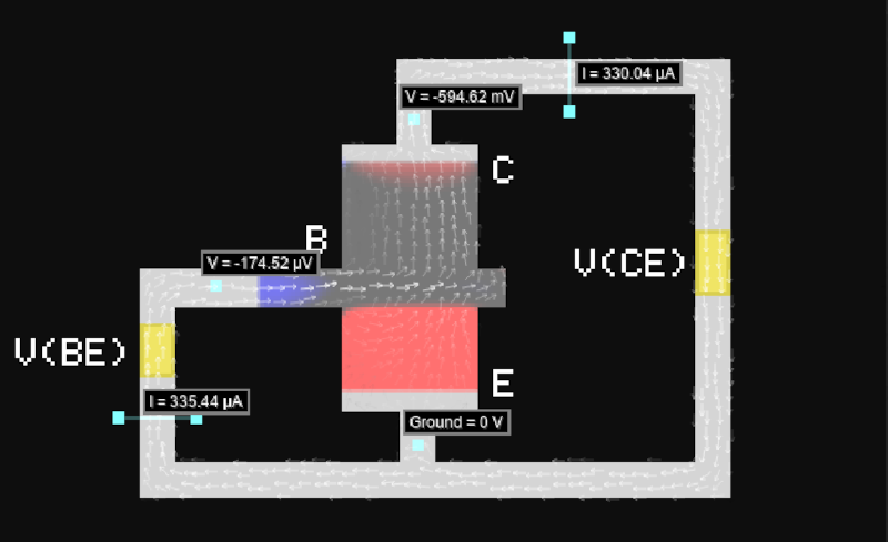
Semiconductor Simulator Lets You Play IC Designer
For circuit simulation, we have always been enthralled with the Falstad simulator which is a simple, Spice-like simulator that runs in the browser. [Brandon] has a simulator, too, but it simulates semiconductor devices. With help from [Paul Falstad], that simulator also runs in the browser.
This simulator takes a little thinking and lets you build devices as you might on an IC die. The key is to use the drop-down that initially says “Interact” to select a tool. Then, the drop-down below lets you select what you are drawing, which can be a voltage source, metal, or various materials you find in semiconductor devices, like n-type or a dielectric.
It is a bit tricky, but if you check out the examples first (like this diode), it gets easier. The main page has many examples. You can even build up entire subsystems like a ring oscillator or a DRAM cell.
Designing at this level has its own quirks. For example, in the real world, you think of resistors as something you can use with great precision, and capacitors are often “sloppy.” On an IC substrate, resistors are often the sloppy component. While capacitor values might not be exact, it is very easy to get an extremely precise ratio of two capacitors because the plate size is tightly controlled. This leads to a different mindset than you are used to when designing with discrete components.
Of course, this is just a simulation, so everything can be perfect. If, for some reason, you don’t know about the Falstad simulator, check it out now.
From Blog – Hackaday via this RSS feed
7
8
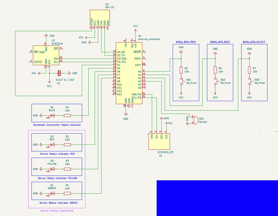
Hello everyone! First off, I need to mention that my background is in Computer Science (this project is actually for my thesis) and not in Electrical or Computer Engineering. As such, everything I've learned has been largely on my own, within the past few months.
That being said, I would feel more confident if an experienced set of eyes could take a look at my schematic and let me know if anything pops out as wrong/bad practice. Furthermore, with regards to the decoupling capacitor on the DS3231M RTC module (C1 on the schematic) I have a question: Would there be any problem if I use an electrolytic capacitor instead of a ceramic one? I read some stuff about the topic and people recommend using ceramic capacitors most of the time (I think) but others say that there shouldn't be a problem to use an electrolytic capacitor. I'm asking because I've already placed an order for parts, and one of them is this assorted set of electrolytic capacitors.
Please if you notice any mistakes or things that are not done the best way let me know, and try to explain why as simply as you can. As I said, I don't have a background in EE, even though it highly interests me and I want to learn.
Here is the schematic:
Many thanks in advance!
9
10
11
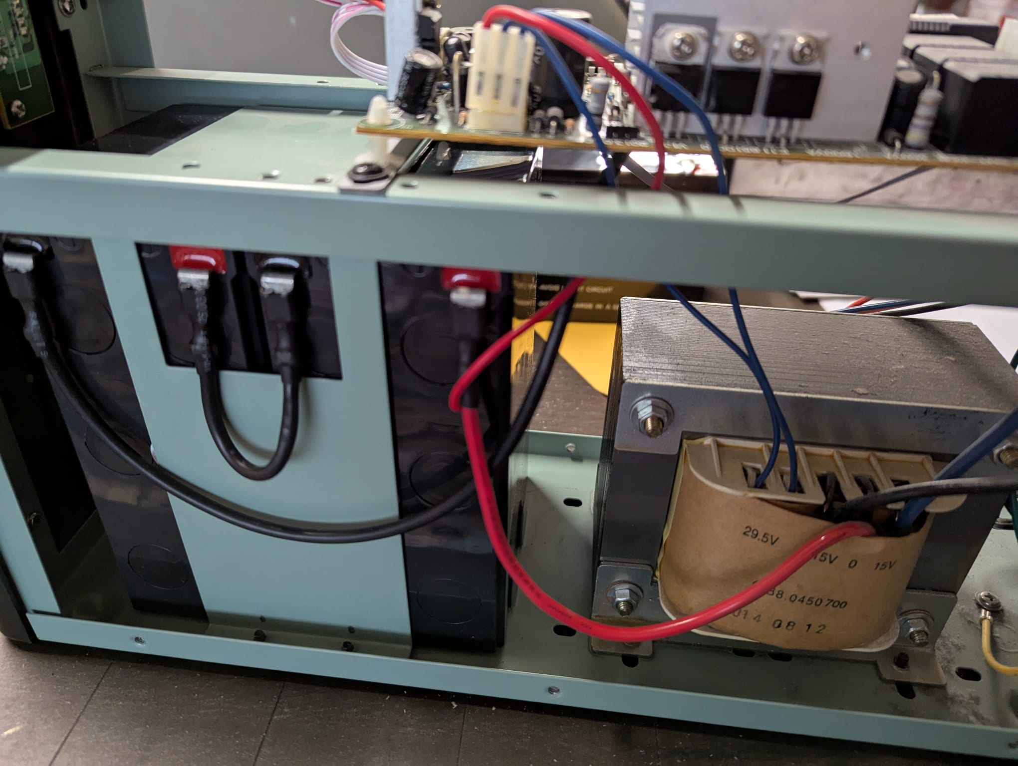
The batteries in this UPS lasted less than a year. It was because those battery were "no name" batteries, or because they were connected in series directly to the AC after the transformer? Shouldn't they have a rectifier and condenser before that? It seems that in this way the battery is connected to AC 24/7
12
13
14
15
17
Just working on my recent electronics project and I needed two temperature sensors for it. This time around I didn't feel like making a full PCB from KiCAD and wanted to keep things simple with a 1/2 size solderable breadboard.
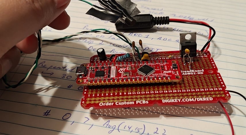
As usual, I'm using an AVR DD (this time: a curiosity nano devboard) for simplicity. (I expect to need the 32768 Hz clock crystal, so a PCB with said clock would be nice. Otherwise, the DIP package is available). The overall circuit is pretty simple, but the topic of discussion today is the MCP970X series temperature sensor.
https://www.microchip.com/en-us/product/mcp9701a
At this point I do recommend people to read the documentation.
The gist is that you simply apply 3.1V to 5.5V between Vdd and Gnd. Vout will have some amount of startup time, and eventually output 400mV + (Temperature-in-C * 19.5mV). For example, my room temperature is ~24C right now and the voltage output is ~920mV.
(There's clearly errors in my ADC but I'm saving that for later... this device is supposed to be outputting 876mV given the room's temperature)
With a ~6uA expected current, this device is power-efficient enough to run from most MCU pins. AVR DD's 50mA-per-pin is overkill, but more importantly, a through-hole design like mine seemingly has substantial inductance on all wires.
The datasheets claim a startup time of 0.8ms. Alas, when I soldered on the MCP9701 and turned on the GPIO-pin, it took over 20ms (!!!) before the oscillating signal finally calmed down and settled upon the room temperature reading.
To counteract this parasitic inductance, I've added a 10kOhm resistor and a 10nF capacitor out of my through-hole kit. (E12 resistor kit and E6 capacitor kit). With 220us of startup time now on the GPIO pin and with only 500uA max current going to Vdd... there is no more "ringing" anymore and life is good!
EDIT: I should probably note that my goal was to return to 0.8ms startup time, like the documents suggest. 10kOhm was chosen as 500uA (5V) to 250uA (after charging to 2.5V) is a magnitude more current than I need and is a decent starting point. 10nF was chosen to pair-up with this to give me startup time in the 100us range but not over 800us (I don't want to be "slowed down" by the charging capacitor, so I want the Vdd charge to be faster than 800us claimed startup time). It should be noted that a 5V over 1000us curve was claimed as a 800us startup in the MCP970x documents if you read all the graphs.
Moving forward, my last task is that of calibration. The on-board ADC of the AVR DD is apparently quite accurate, but the Vref of the microcontroller is +/-4% (!!). With a +/- 2% accuracy of the temperature sensor, there is some calibration I should do.
The ADC errors + Vref errors are expected to just be linear. The temperature-sensor's error is quadratic however. In both cases, I don't want to overcomplicate things, so I'm planning on just adding a constant-offset to the mV reading to shift it to the correct spot.
All in all: pretty standard Analog-to-digital conversion issues here. But I figured it'd be a good discussion topic for beginners.
18
19
20
21
What really interests me about this design is the ~~buck~~ Boost-converter
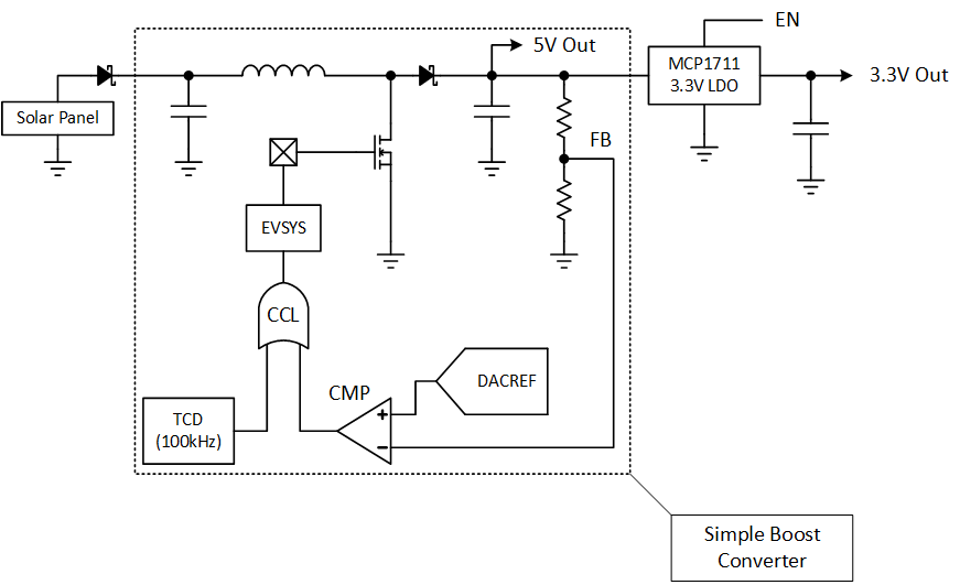
So this ~~buck~~ boost-converter is 100% core-independent. The Analog Comparator, TimerD, CCL, and Event-System are all active while the AVR DB sleeps, meaning that the microcontroller can run this simple ~~buck~~ boost-converter without any cost to CPU time.
An incredible design that demonstrates the flexibility of AVR DB's combined peripherals.
22
23
24
6
How to use I2C devices in (Apache) NuttX: Adding support for an I2C device in your board
(www.embeddedrelated.com)
25
view more: next ›