Ask Electronics

3742 readers
1 users here now

For questions about component-level electronic circuits, tools and equipment.

Rules

1: Be nice.

2: Be on-topic (eg: Electronic, not electrical).

3: No commercial stuff, buying, selling or valuations.

4: Be safe.


founded 2 years ago
MODERATORS
201


I'm trying to repair an arcade PCB with intermittent audio. The board on top is the audio board, the bottom board is the everything else.

There is a short or poor connection somewhere in this 96 pin DIN, press-fit connector.

I have OEM replacements, and would like to install new ones, but really have no idea how to do it properly (if you can even do it properly). My first thought was to do the following:

  • Physically cut the pressfit connection to remove the plastic housings
  • individually remove each cut pin from the PCB
  • 3D print a "frame" around the connector area to minimize PCB flex, and use an arbor press to insert the press-fit connector

If anyone else has suggestions, I'm all ears!

202


I'm trying to replace the jet engine fan inside the PSU of a Nu 1.1 with a Noctua equivalent and am having trouble identifying the connector. The PSU is a Delta Electronics Model EDPS-250AB A, Part Number 400-5494-91.

I have taken several pictures of the fan connector and its header in the hopes of identifying the connection. I originally thought it was a JST-EH 2.0, but it is not, and the only means of comparison that I currently have.

Photos here: https://imgur.com/a/JQVahV3

Please help!

203


My room thermometer is consuming a full stack 3 AAA batteries in just 24 hours. I opened it and found that maybe the component circled in green is burnt (CAZB).

Can you please help me identify what it is in order to replace it?

Thanks!

204


I lost my electric fence tester, probably the pigs ate it. But I opened it once to resolder the earth wire and found it's really just a voltage divider with resistors and leds, so I can probably rebuild with stuff I have. What resistor values though? 2k to 10k V run through the fence. If any of you good people have a diagram, a formula or an idea, please help.

205


I wanna run a HR202 moisture sensor and an Arduino. Yes, I picked a HR202 to challenge myself to make it work. I already have some easier-to-use SHT40 in stock.

This sensor can only run with AC 1.5Vpeak max. So, I've created this little circuit to provide AC, and I'll only read it when the oscillator output is HIGH, so I can read it briefly at the same time with the help of Arduino's ADC. Could this circuit work? Thank you.

206


Here's a power cable from a Cmt-ex1 Sony CD player. This connector used to be connected to the inside of the power supply. However, I had to disassemble it because I needed to replace the motherboard for the CD player. I found this CD player at Goodwill, but the wire was poorly connected with a completely different cable. It was patched together using electrical tape and wire connectors. If there isn't any type of connector like this in the world. how could I Frankenstein it with another cable without it looking somewhat ugly.

The original cable was called E81093 (UL) NISPT-2 VW-1 105C 2X18AWG, C(UL) NONINTEGRAL SPT-2 FT1. Also the yellow plastic says Amp with a + on top of the M. this CD player is from 2000.

207


I want to use an IC that will take x4 3.0 PCIe lanes, and adds a USB 3.1 controller.

This ASMedia one looks ideal, but doesn't appear to be available to the common folk: https://www.asmedia.com.tw/product/E0CYQ4fSpaQxdjzA/f32YQ14SmApn1wNA

There's also https://www.ti.com/lit/ds/symlink/tusb7340.pdf - but that costs 22USD with LCSC, as well as being much slower (only using x1 lane)

I'm finding it hard to Google as well, because it seems to bring up complete products rather than ICs.

Can buy a whole card on eBay with the ASM3242 on it!

Can anyone help here please?

208


Mates bread maker stopped working so I had a look inside and saw this burned resistor.

I'm guessing the heat changed the colors a bit so wondering if anyone has experience in reading cooked resistor values.

I removed it from the PCB and measured it at 403 Ohms.

Thanks for any help.

209


Hello everyone! I'm designing a PCB and I have some doubts about how to connect the 4 resistors at the top to capacitor C34. They are 4 traces, and all of them terminate at the same pad of the capacitor. As I have currently placed them, are they connected correctly? Or should I connect them in a different way?

210


My goal is to drive an infrared LED like (this SFH 4727AS) to control IR remote controlled devices (for example a TV).

I can already output the signal on a pin of my microcontroller. The signal has a carrier frequency of 38kHz.

I am however limited to a 5V 1A power supply and would like to drive the LED as close to the 5W psu limit as possible.

I first thought about using a MOSFET like this AO3400A together with a resistor, but decided it was worth using an LED driver, do you agree?

Now I'm looking at this PAM2804 constant current LED driver but I'm not sure if I can just supply my signal to the EN pin. The EN pin is meant for PWM-dimming, so does that mean the output is smoothed to prevent flickering?

I'd love to hear your thoughts about how I should go about this. Thanks

211


First of all, I apologize for the lack of a "formal" schematic... I tried to draw one out, but got buried in the nuances of it :)

Second, I've done enough research to have some idea of what my problem is: namely, I need a decoupling capacitor in the mix. Problem is, I'm new enough to this that I'm not 100% sure where to put it, nor what capacitance I should use.

So the setup: -I'm using a Wemos(like) D1 Mini to drive 8 relays via an HC595 shift register -The D1 Mini microcontroller, HC595, and relay module are all powered by the same 5V DC and ground -The microcontroller addresses the shift register via 3.3VDC data pins -The relays power a water valve via a separate 24VDC power supply and transformer - plugged into the same AC outlet

And the problem: everything works just fine UNTIL I actually add the 24VDC power load. Once that's done, the results are very erratic... usually turning on the correct valve correctly, but rarely turning it off in the same way. As I mentioned, I intuitively suspect noise in the data caused by the sudden power to the valve... but it doesn't make too much sense since everything is on different power supplies.

Any guesses as to where I need to put some capacitor(s)? Thanks!!

212


Hi, I found an old cellphone battery (from a Pixel3A phone) and I'd like to reuse it for my robotics experiments. (link to images: https://imgur.com/a/Oj09tai)

2 questions:

  1. how can I trasform the output connection to a more "standard" output connection (ideally V+ and V- wires)
  2. how could I recharge the battery?

Any safety concerns, other than don't poke it? :D

213


If I wanted to make a USB desk fan from a spare CPU fan (input: 12V, 0.15A), could I just solder a resistor to the positive lead of the USB wire? I plan on getting an adjustable voltage booster, but I was curious if this was possible. I think I would need a 13 ohm resistor for USB 3.0.

214


I am looking for a Toggle switch that will allow me to actuate an actuator manually, or otherwise set the actuator to an 'automatic' mode, logic for which which I am coding on an arduino. The switch I want should have momentary On's for manual trimming that will spring back to an Off position, or it can be left in another maintained On position to signify the automatic logic should take over.

I had in mind something like a 2-axis Toggle switch that will have in the X-axis an MomentaryOn-Off-MomentaryOn configuration which will allow me to trim when in manual mode, but there should also be a fourth position (3rd Throw) above or below the 'Off' which would be a maintained On. Hopefully my diagram below explains the kind of switch I'm after too:

       On
       |

(On) - Off - (On)

I have spent about a day searching for something like this, and the only things I have found are a few old Cutler-Hammer aviation switches which seemed to do exactly this (8905K514, 8905K671, and 8905K608), but these are rare and expensive, and I wanted something I could easily get spares for.

I know I could achieve similar using a combination of two or more switches, but I feel it would be more elegant to have one switch that does everything. Does anyone have any suggestions?

Thanks in advance!

215


I bought a PWM Dimmer based on a 555 from AliExpress to regulate the brightness of a 12V 1A 1 meter LED strip, I already built one myself years ago on a perfboard but this one was the exact dimensions I needed for a project. I built mine from components from AliExpress and components found in old electronics so I thought nothing functionally would change The dimmer is this one https://www.diymore.cc/products/pwm-10a-speed-regulation-led-dimming-ultra-high-linearity-band-switch but I attached a real photo of the one I got from AliExpress My problem is that it isn't doing any regulation while connected to LED strips, I tried with the 1m one and with another light that has three 30cm LED strips in parallel Every other light or motor I connected to it seemed to make it work. I really have no idea what could be causing this, maybe it's sensible to capacitance? LED strips are two long straight parallel contacts but I don't think it's enough to cause anything as displayed here in the video: https://live.staticflickr.com/video/53017878188/54f865d36d/1080p.mp4?s=eyJpIjo1MzAxNzg3ODE4OCwiZSI6MTY4ODMxNzgwMCwicyI6ImI2MjZiMzk3MjExNTQxZWIyOTYwYzAyNTRmZDNhZDZjZTcwOWUxOGYiLCJ2IjoxfQ

Please no prejudice on that oscilloscope, it's good for what its made for, it's "calibrated", it shows a clean square waveform on my simple diy dimmer (photo to let you see what I mean with simple) versus what is shown in the video with the AliExpress one, an hybrid ramp/square. In the first part I show one of those LED strip that doesn't work, in the second part I show one that does work, just like every other light or motor I've tried

216


I tried adding an AUX jack to a car stereo with an internal CD player and no native support for one.

When I first did tests, simply attaching to one of the amp's input lines while the stereo was at min volume (1, not 0, more on this later) worked wonderfully.

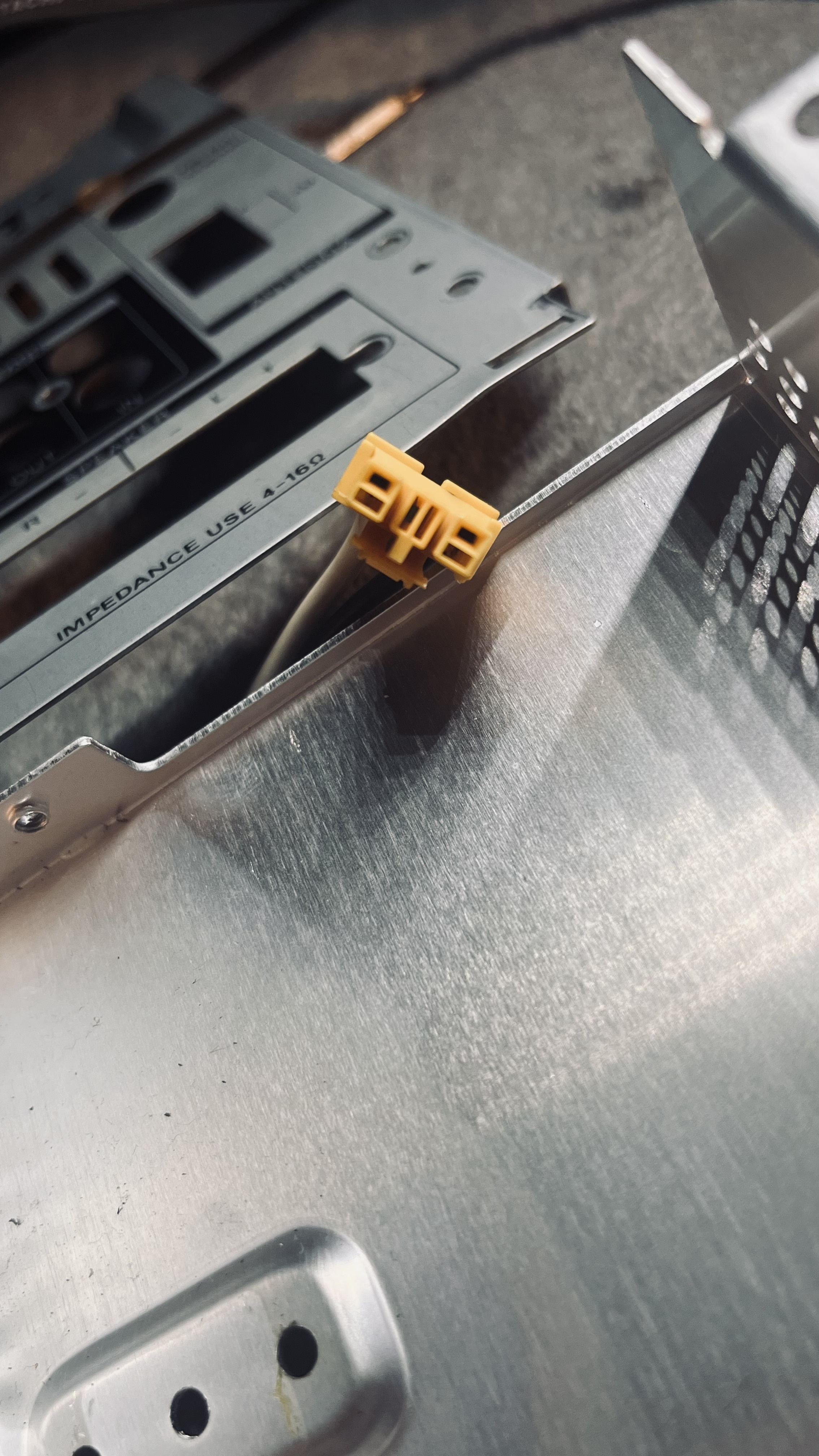
To install the jack itself however, I thought that it may be dangerous to have the stereo send current to the AUX device and vice versa, so I thought about installing a switch to cut the stereo's audio input lines when using the jack and vice versa.

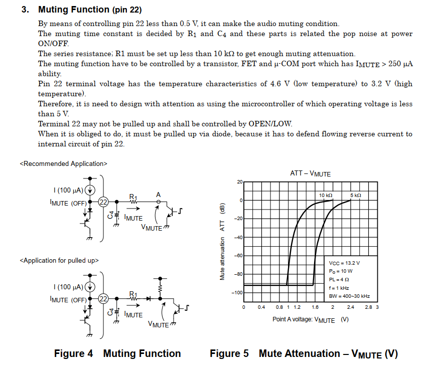
I thought about just muting the stereo, or turning the volume to 0, or using a dummy paused CD, but all of the three activate the mute line on the amp, which isn't a simple binary on/off deal, and activating it would also mute the jack.
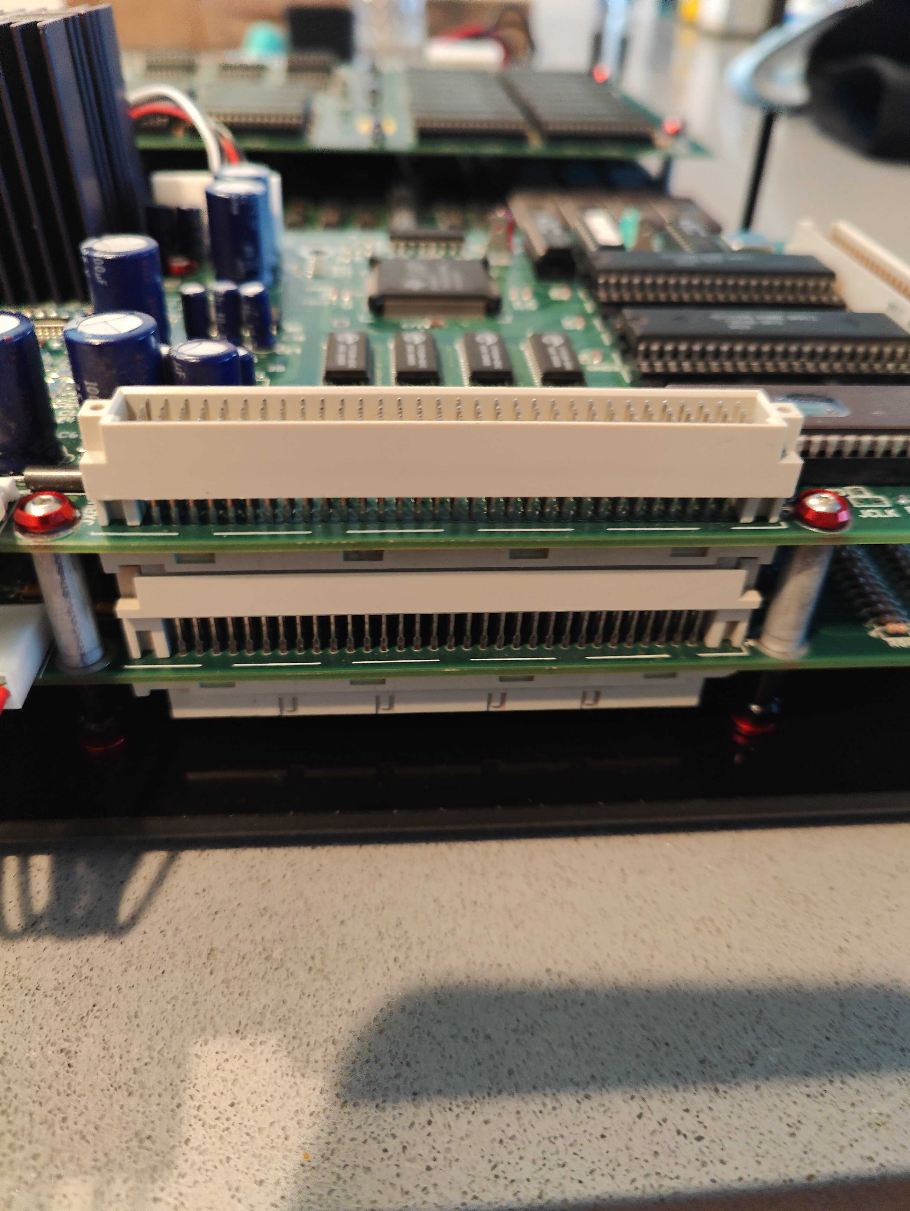
Image

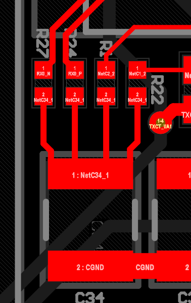
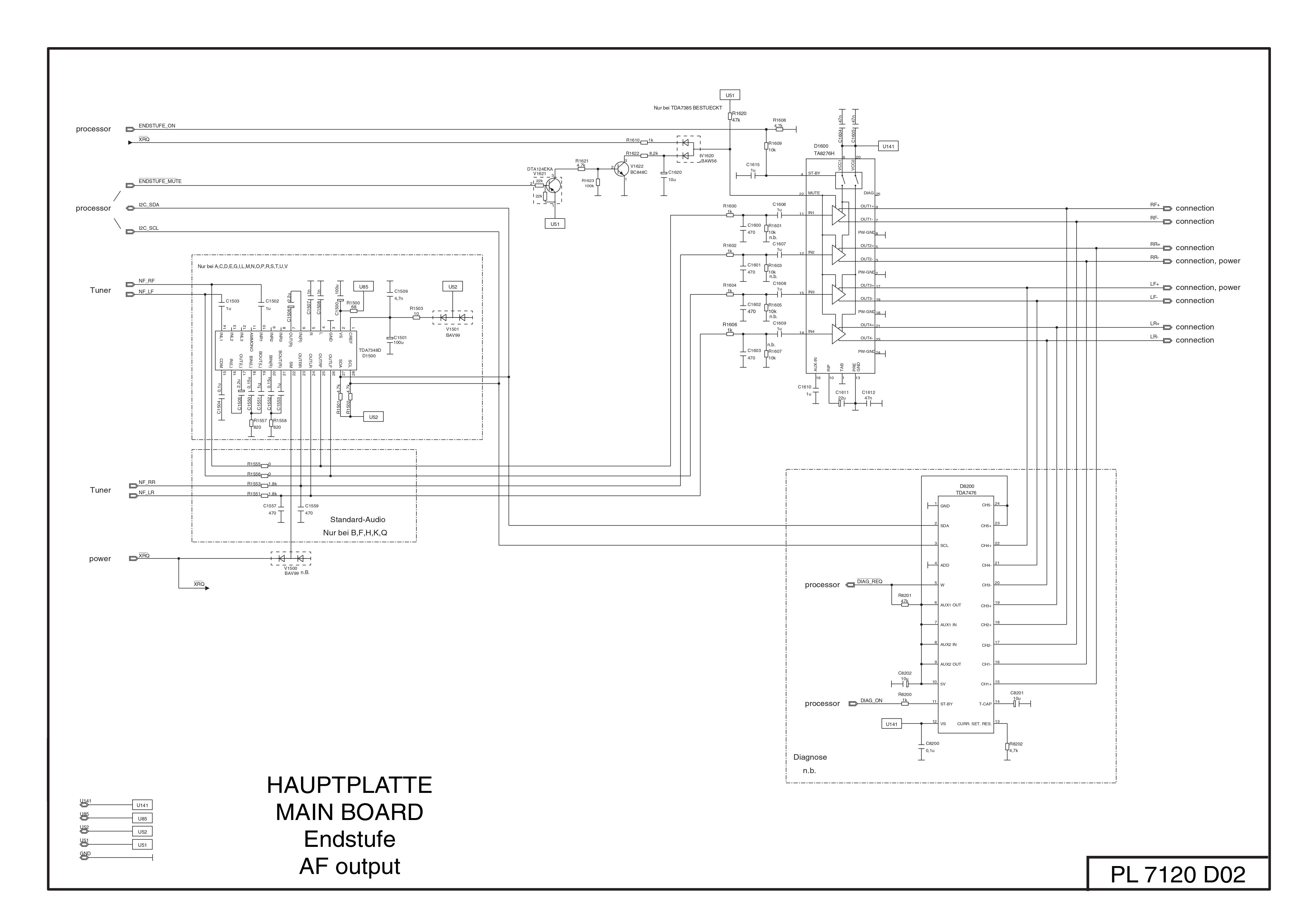
This is the original schematic of the amp circuit: Image
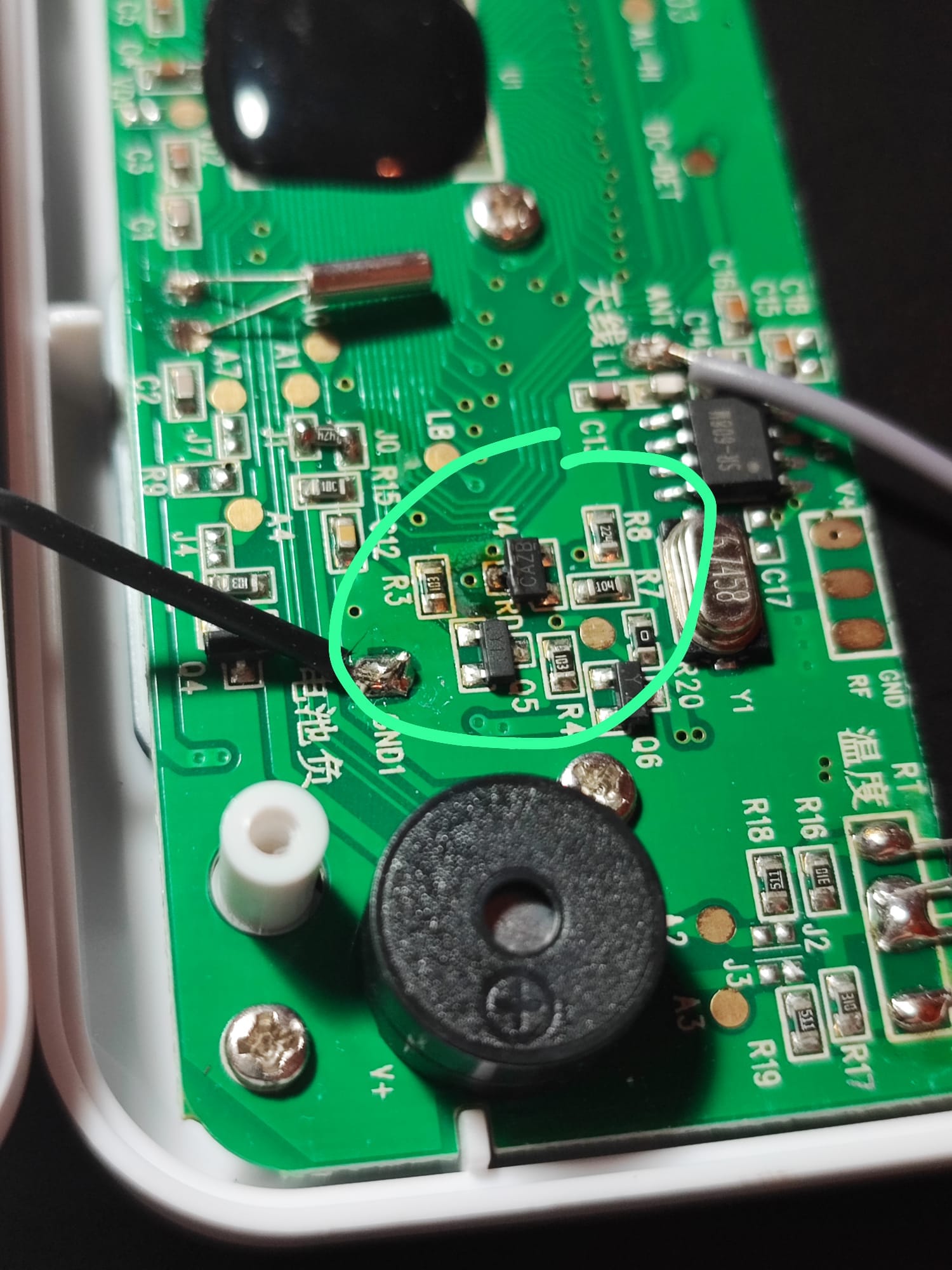
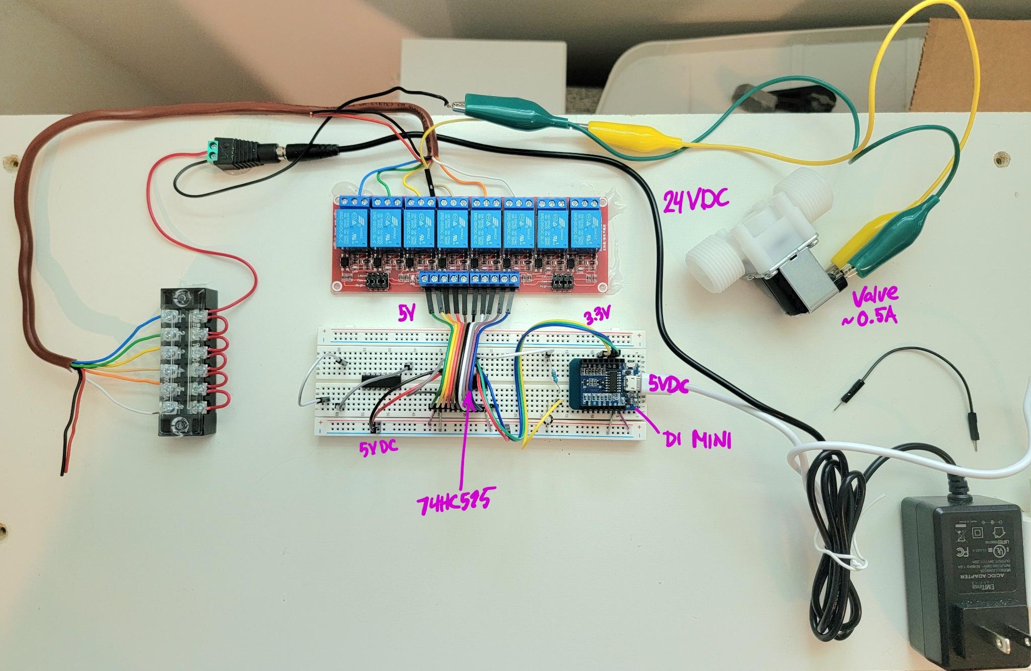
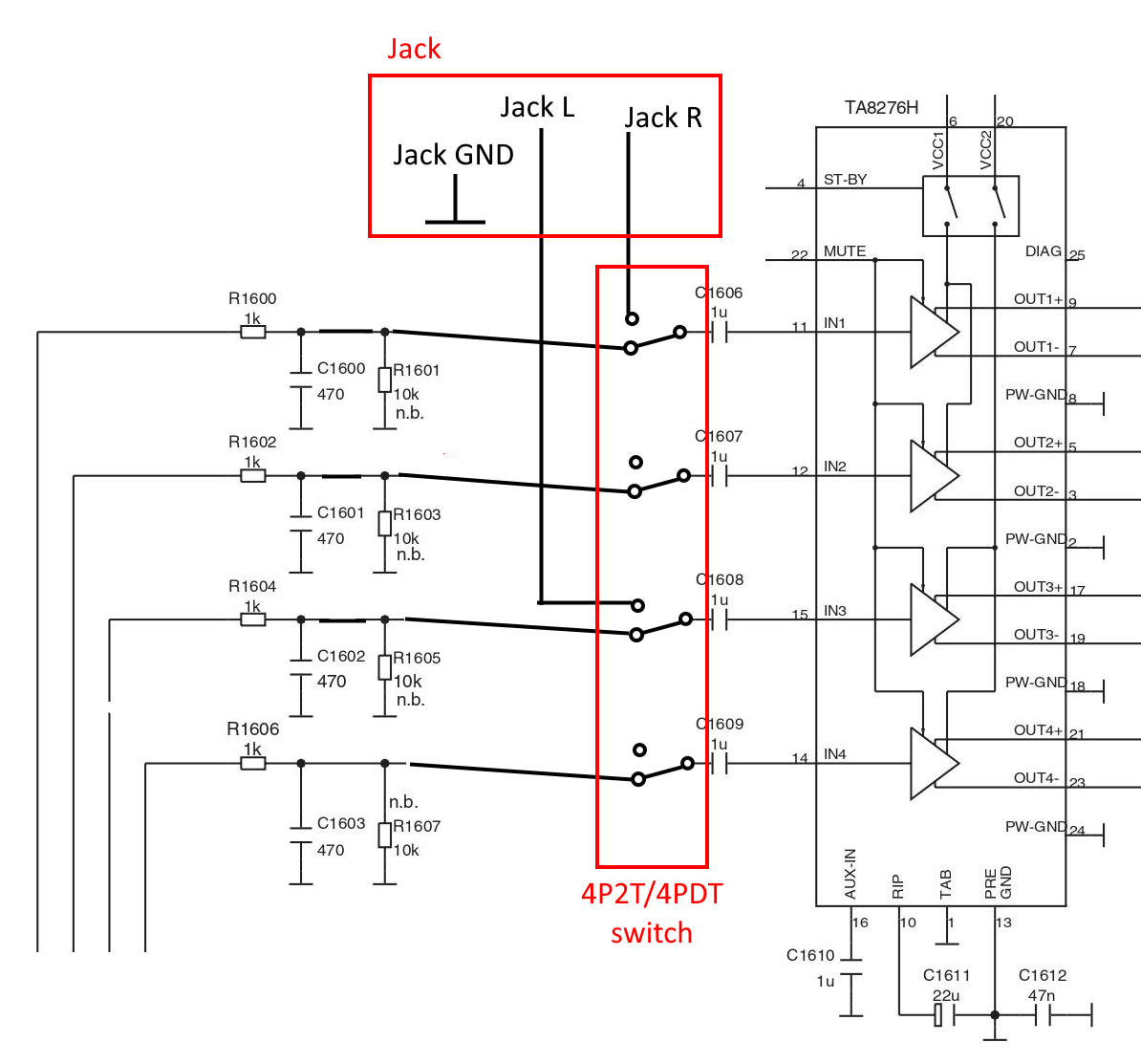
I attached to the IN1-4 lines like this: Image

I left the rear channels disconnected because a friend of mine suggested jumping two input lines could cause issues to the amp

However, once all was done, it wasn't working correctly. First of all, when I flip the switch, some signal from the stereo still gets through. It's very faint and you have to turn the volume way up to hear it, but it's there. This concerns me if it may lead to damage to either the plugged in device or the stereo, and if it could be the cause of the following issue.

Second, when a male to male cable is plugged in the other end (without even anything attached to the other end), a high pitched whine starts playing from the speakers. I tried bypassing the jack with alligator clips to the rear terminals, but it still happens, and when this happens I suddenly read a resistance of 7~8MΩ between either of the jack's channels and ground. I haven't tried another cable, but if I test the cable itself when it's unplugged I can't read anything between the rings.

I'm especially puzzled as to why there were no issues when I tried by tapping into the lines, but now that I did it """properly""" (at least in my head) it's problematic.

The full schematic for the stereo can be found by googling "BLAUPUNKT FIAT B-MPV CD-MP3 7645324316 SM"

217


I have a 12v 6.67A power supply with a male co-axial plug (with centre pin) that's 7.4mm OD and 5.08mm ID. The metal tube is 12.5mm long.

The pin is recessed and about 1mm in diameter - which seems impossibly small for 6.67A.

A chassis mount socket that would take it would come in handy. But I don't seem to be able to find one. Am I just using the wrong search terms?

Any pointers much appreciated.

218


So I wanted to design a children's toy, where the electronics could last 100 years (ignoring mechanical abuse). I figured some people here might be interested.

I settled on a CR2032-powered night light, using an attiny10 microcontroller, where the flash is rated for 100 years unless you're writing to it (which I am not). I did some pretty heavy power optimization. The firmware is hand-optimized assembly.

When you turn it upside-down, a tilt switch toggles an LED @ 3mA via a pretty intense debouncing routine.

A watchdog timer has it auto power off in 30 minutes.

When off, it consumes less than 1 uA. So it has about 25 years of standby time, although the battery is only rated for 10 years (it is replaceable though).

If a child uses it every day, then the battery should last about 4.5 months.

I made custom boards for it -- I kept is simple with few components as possible (resistor is for scale):

I kept assembly simple. A better design would snap right in to the pins of the CR2032 holder, but that's an addition I'll make another day. I also should have added one more ground pad to solder to, but forgot. Still, an OK result I think.

I used some spay-on lacquer to protect the traces a bit after assembly.

219


I want to connect five OV2640 cameras via FPC to an ESP32 on a custom PCB. Is this generally possible and does the ESP32 have enough power for this or do I need an ESP32 for each camera? The frames per second are not so important as the cameras will be used as QR code scanners. Which components allow to run so many cameras with one ESP32?

220


I'm looking for a version of this connector (2x2, 2.54mm):

https://www.adafruit.com/product/4855

with extra long pins, like this: https://www.adafruit.com/product/2223

Any sources for this?

221


A comprehensive mapping of old subreddits to new communities.

222


Since I never understood op-amps from reading or practicing problems I wanted to build a circuit to probe around and use different resistor values to set the amplification.

Currently I am attempting to build an LM358 Non-Inverting Op Amp. I am using my power supply for a +/- 12V rail, and my Arduino Uno for my 5V supply at the V+ input pin. I have chosen two 1k resistors to amplify the signal to 10V at the output and put and led as a indication that the circuit is working.

My questions are as follows:

  1. Is the ground for the voltage rail and input signal the same?
  2. What exactly is wrong with the circuit I built? I want the LED to only turn on when 5V is supplied at the input, right now the LED can turn on if I connect the ground to the voltage rail supply even without an input voltage.
  3. I've seen the post on Adafruit with the feedback resistors connected to the same ground as the rail supply, but the circuit diagram does not show where the input voltage ground is? Link: https://blog.adafruit.com/2012/06/13/ask-an-educator-making-a-non-inverting-op-amp-circuit-on-a-breadboard/
223


Is there a reason why the banner and logo of this community are just the reddit logo?

To be honest that doesn't seem very appropriate, nor is it very pretty.

224


What I've done is take a large 2n3055 BJT NPN power transistor, and decap it (it is a large metal-can type). Then I carefully removed any coating from the exposed silicon (it typically has a dab of silicone potting compound on it).

Then, I had a weak alpha source at ~5MeV lying around the lab from previous work. This was inserted into the can with the beam facing downward towards the exposed silicon, and the can reattached and made lightproof.

Then I threw together the circuit shown here using the modified transistor (the base is left floating). What I expected to happen was that at TP1 (relative to GND), with my scope AC-coupled, I should see small voltage spikes followed by a decay. This is caused by alpha particles impacting the silicon and knocking loose enough electrons to permit some current flow.

However, I just see... more or less nothing, maybe some electrical noise from fluorescent lamps in the room next door. Certainly not the spike+decay curve I've seen with other detectors.

Did I make a wrong assumption somewhere? It's been a while since I worked with discrete transistors much, and I feel like I am missing something silly.

Or is this more or less right, and I should maybe question whether my alpha source is still good? Or whether the signal strength is in a voltage domain I can even clearly see without amplification? Or maybe I should suspect that a thin passivating glass layer is added to big BJTs these days, enough to block the alpha?

The source is past expiry, but not by that much. I'm mostly interested in characterizing and documenting the detector as an academic exercise.

225


I've wondered this occasionally over the years, but never got it working.

I tried just putting a dried piece of chicken bone pressed between two plates (mild compressive stress perpendicular to the bone), and using an inverter just like I would use a crystal. It did not work. Maybe I need a really thin segment?

I have no practical application in mind. I might make a CPU from it for Halloween I guess?

I'm not sure if I would classify it as electronics or necromancy, but I thought it was an interesting question to ask here :)

view more: ‹ prev next ›