Ask Electronics

3742 readers
1 users here now

For questions about component-level electronic circuits, tools and equipment.

Rules

1: Be nice.

2: Be on-topic (eg: Electronic, not electrical).

3: No commercial stuff, buying, selling or valuations.

4: Be safe.


founded 2 years ago
MODERATORS
126


So, there are these great 32700 LiFePO4 batteries that showed up in my local industrial market. For like USD 2$!

However, there are no LiFePO4 chargers available. The vendors assure me I can "totally use" a 4.2V Li-ion charger, but I don't believe them (although the cells test as being in good shape).

I whipped up a 5V system with a buck converter managed by an MCU. It turns off the buck converter that charges the battery, measures the battery voltage, and if it's under 3.6V it enables the buck converter. Repeats every few 100s of milliseconds.

Did I overengineer this? Could I have just used a linear voltage regulator that outputs 3.6V (or a Zener), and a current-limited 5v power supply?

Charge speed is not really important in my application. Anything under 4 hours is great. Frankly, I'm just trying to phase out the less safe kinds of lithium cell in my lab.

127


I had an old USB Oscilloscope (StingRay), it's 20+ years old now.

Bought a OWON HDS242 with the hope that I could view some stuff on it's screen, but still hook it up via USB to the computer and do some voltage data logging. It doesn't seem to work like I would like it to.

So I've learned what I want is a Data Logger and not an Oscilloscope.

Can anyone recommend a good USB Data Logger that won't break the bank?

Decent bit ADC, and something that can get down to the 1us.

Doesn't need to be high voltage.

Cheers,

128


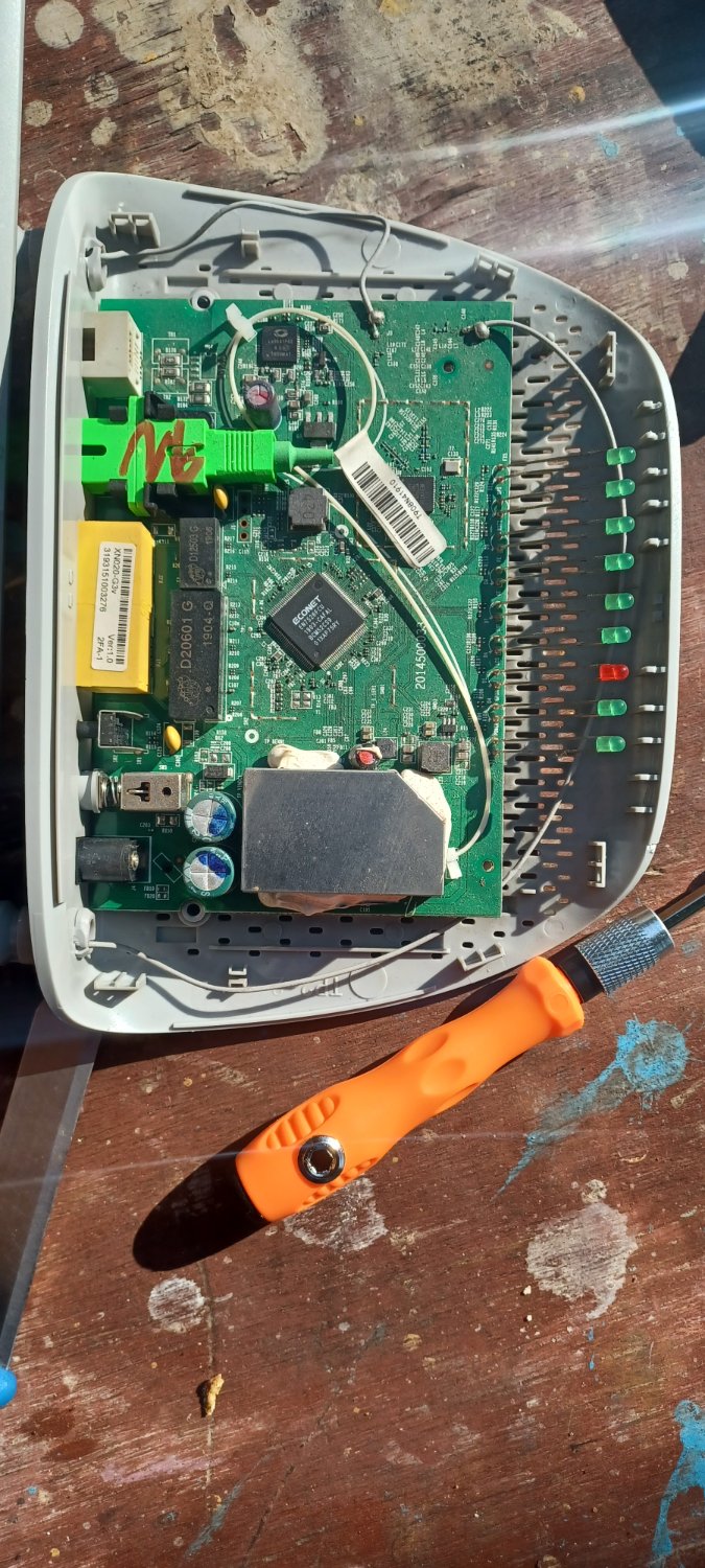
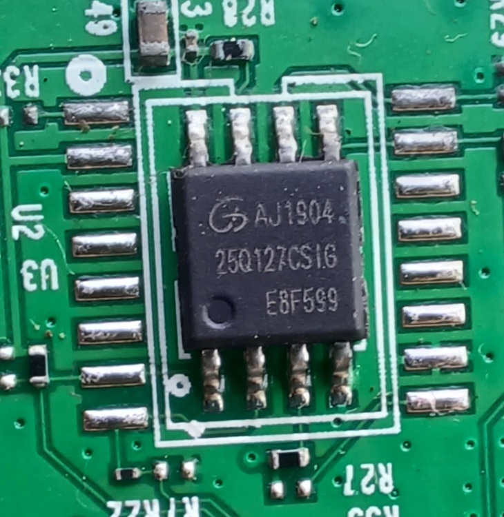
Just exploring about this tp-link XN020-G3v router. I'm mostly interested in connecting to the UART, won't be tinkering with electronics of it, but out of curiosity I tried to search what these chips are. and I couldn't find much about the big chip. Can anyone describe the 4 main chips on it ? Best would be datasheet, but whatever information you can provide.

I suspect

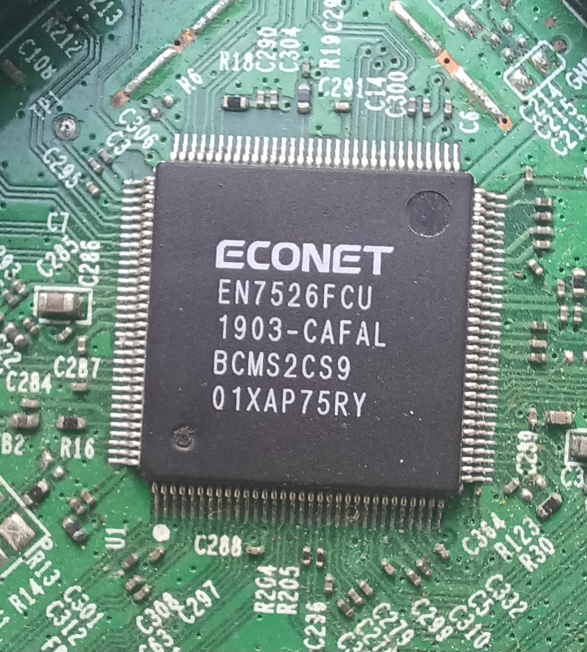
  1. bigger one(ECONET EN7526FCU) is CPU/SOC, (couldn't find datasheet/specs). Can anyone provide details ?
  2. MT7592N is definitely network IC(found datasheet)
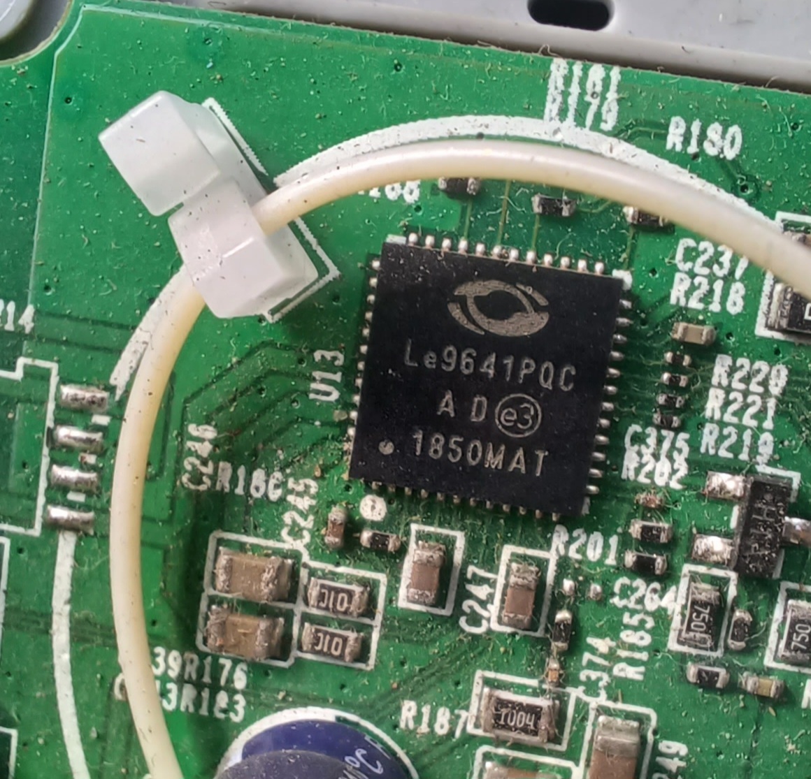
  3. Le9641PQC is network IC. required for VoIP. (found datasheet)
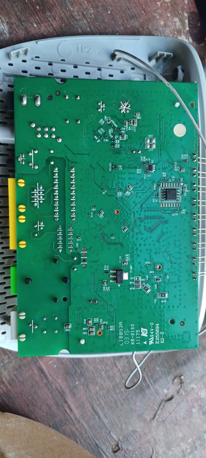
  4. AJ194 (backside) is flash ? How to tinker with it ?

129


I migrated here in the US (specifically in San Bernardino, CA). Quick Intro: I'm a graduate electrical engineer; honestly, I really don't have that much experience and not even a decent internship experience due to covid, resulting in an online OJT. Do you think doing an internship here in the US is the way to go? If yes, what kind of advice can you give when applying like tips and what things should i look into, and what kind of internship should I start with? Thank you, any advice are appreciated :))

130


hi again, since i had a bad idea in my last post i wanted to try again to get some feedback i could understand and apply.

the idea is to make a vacuum (the appliance) play a few seconds of r2d2 sounds. the vacuum is hauled around on the scaffolding on a construction site and wont be necessarily standing upright (while idle or in used).

my original idea was to have some kind of trigger through a sensor (SW-18010, or something) that draws zero power (like a tilt switch, but position independent). that trigger should pull a pin high on the dfmini mp3 player (cheap player board) which in turn would play a few audio files while powered.

so sensor -> 555 astable -> df mini player -> speaker (piezzo maybe).

any ideas or pointers? is the idea of zero power in this case even possible (never used the 555 before), is maybe a attiny a better idea while in deep sleep?

battery life of 1year + would be ideal.

131


My Google-fu has completely failed me. I've got an RGB addressable led curtain. It has 20 strings of 20 LEDs in a square arrangement. I initially assumed it had a wire feeding led data back up, to go to the next drop. On checking however, they are T jointed.

Apparently the address is hard coded into the RGB controller in the LED. I've found a few places where others have talked about them. I've also found that adafruit had some available,, unfortunately they lacked any info on how they are programmed, or where to source them from.

https://www.adafruit.com/product/4917

Anyone got any info on what the chip name of these is? Even better if you have any info on how they are programmed etc!

132


To all the electronic nerds out there: I am trying to trigger a 555 timer by movement in a random direction that also occurs randomly and any change in position should trigger the 555. AFAIK tilt switches are not useable here. Does this idea make sense?

Ferrite core In orange, spool in blue.

Would there be a voltage generated by movement if the core is suspended by some kind of spring or rubber band?

The idea being to play a sound from a df mini player by pulling a pin high for 3 seconds.

133


Im building a flashlight and i want to test if a fan in it would be a good idea but the flashlight is really small so i would need a motor thats smaller than 1 cm preferably. I found really good ones at maxon group but unless you order them in bulk(1000+ units) they cost like 400€. So do yall know anywhere i could find them? Thanks in advance! (Edit: Im a complete baffoon and forgot to specify that preferably i would need a water resistant fan. I assumed this because bldc motors without drivers are wter resistant)

134


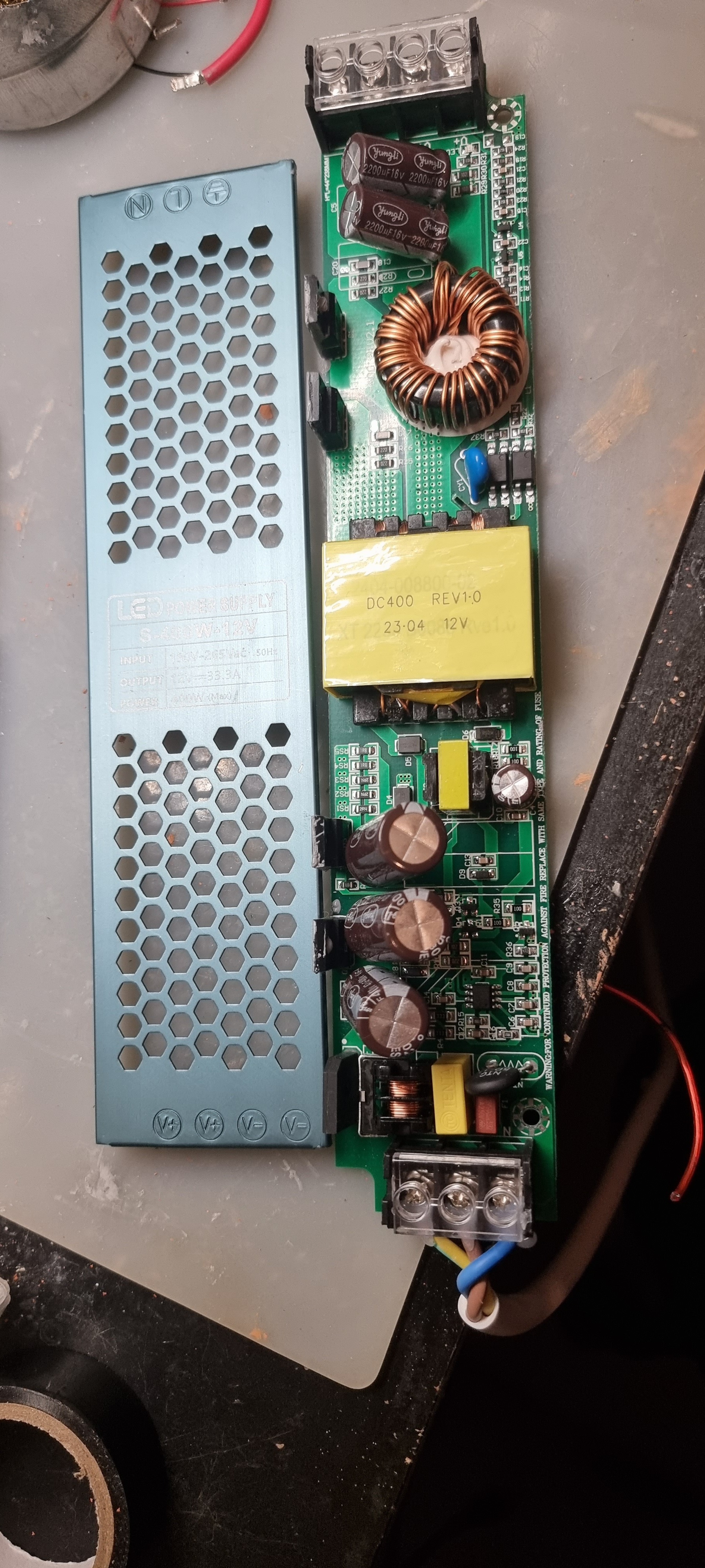
Does anyone recognise these power supplies? They're cheap AliExpress led drivers and I want to change its output voltage to around 22V from 12V. I've read that the way to do this is to adjust the REF voltage on the IC that controls it. It's a KA3845 but I don't understand where that reference voltage is regulated. One voltage is feedback from the output where then other should be a reference.

What would be the best way to approach this? I can't find any schematics on these boards unfortunately.

Thanks.

135


I have a 3D printer and have a special filter that has two 24V blower fans that are connected in parallel. Unfortunately my printer doesn't have the proper connectors for the fans. So if I purchase something like this power jack adapter I know the adapter is 12V not sure if that would make a difference. Anyway if I connect the female part of that adapter to the fan cables and plug in my laptop charger which is rated for 19v to 24V would that be ok?

If those adapters are fine, should I just purchase 12V blower fans instead?

136


Hi,

I recently bought a few pre-made amplifier modules for an 8-channel amplifier project (for a sound installation).

The amp is based on the TDA7294 chip and is rated 85W nominal. Now I'm looking for a power supply, but I'm a bit lost (this isn't really my strongest field, to put it mildly).

Do I just need to add up the output power, 8*85W = 680W, or could I get away with using something smaller, like a 300W or 300VA?

Also, the seller said that you need to use CV power supplies, CC won't work and kill the circuit. Does that mean a switching supply can't be used?

It looks like the module has a rectifier and smoothing caps integrated, so I could potentially just use a transformer, right?

Best, N

137


I have to fix a slightly very stupid mistake that I've made.

I'm trying to recreate the conductive lines of a membrane keyboard, unfortunately after trying to unglue them they got ripped off, I've painted 2 coats but it I'm receiving no signs of life from it.

Is Liquidwire the wrong paint for the job? Maybe the circuit lines ar too long to fix? Should I try copper or silver paint?

I've read online that shaking the pain is not enough and that I should also stirr it.

138


I have two led strips used for 2x27" monitor bias lighting. Each have their own USB cables for power. These two USB cables are plugged into a 2-port wall charger for a phone. I would like to use a 2x female to 1x male adapter to join the two USB cables into one, then plug it into a much smaller 1-port USB wall charger. The reason is due to my space constraints.

Will doing this impact its energy efficiency, ie using an adapter like this?

https://www.aliexpress.com/item/1005004340044483.html

139


Hi, 
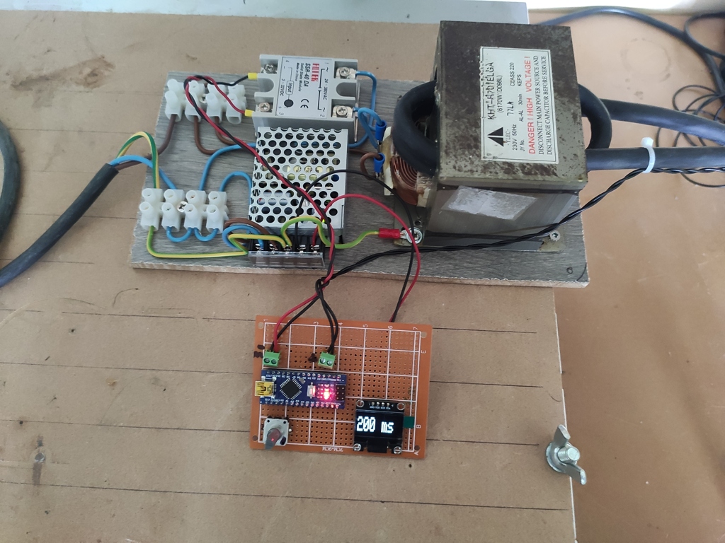
I have built a microvawe transformer spotwelder, I have put a single turn of welder wire for in the secondary and I'm timing it with arduino. Worth mentioning it was/is a 230V transformer. Electrodes are sharpened copper rods. I believe the voltage is still high. The spotwelds it produces are slightly discolored and not as strong as you would expect. Is this design fundamentally borked? Is there anything else I can make to make it better? Photo from test stage before it was built into a project box, it is less "shocking" now.

140


Currently, only one company in the world -- ASML -- has the technological capability necessary for the creation of photolithography machines which are sufficient for the production of modern semiconductor devices. What I'm wondering is at what point does semiconductor manufacturing become practical, or even feesible for small organizations, or independents? One must be able to surpass the cost of the machines, and the resources necessary to manufacture them. I presume that a company like ASML is also extremely picky -- willfully, or by regulation, or otherwise -- about who they lend their technology to.


I'm not sure if this is the right community for this sort of post. Please let me know if not, and if there is a more suitable place to put it.

141


Hi!

I've asked Siglent support but after a couple of responses the thread went cold. Maybe I'm being dumb but I've noticed that there's a frequency (low, around 100Hz) where scope response changes a bit. Below and above it square input looks square. Right about it square input looks slanted.

I tried to do a very slow "sweep" and there's small but visible change in the envelope. So, e.g. with a constant 600mV p2p input lower frequencies measure exactly that while higher ones measure 612mV, so ~2% diff.

Terminated 50Ohm cables (not that it matters at such a low freq) to be sure. Latest firmware, after full self-cal. Siggen itself seems allright, I have an ancient Tek scope and the siggen output looks Ok there with same input/same cables. Scope seems happy and fully functional otherwise, few years old though, out of warranty.

Has anyone else seen anything like that? Is this a normal behavior within the expected margin of error?

Thanks!

142


Hello y’all! I’ve always been interested in computers and programming for as long as i can remember, but recently i’ve decided to try to get into some of the deeper stuff behind that, into the wonderful world of electronics. Where should I start? What courses or books or youtube series should I consume? What are some high-quality forums, communities, blogs, etc. to learn from?

143


I'm working on an Arduino project that will likely rely on a 9v for its power. If I can get at least 40 hours of power, I'd be happy with that. Here's why I think it's doable:

First, rechargeable 9v lion batteries nowadays have substantially higher capacities than even a few years ago. I see one on Amazon rated for 5400mWh!

Of course, I'll want to reduce power consumption as much as possible, so I'm thinking an Arduino micro would be the best choice (though I will be attaching a shield to it, which will add to the current draw.

My understanding is that the linear regulator on the Arduino is capable of reducing the 9v down to 5v, but at great expense to efficiency through heat loss. My thinking was to bypass the linear regulator entirely, and rely on a much more efficient buck converter to adjust the voltage down to 5v.

Thinking it might be possible to reduce the core clock as well, and run the Arduino at 3.3v instead of 5.

Anything I should consider that I might have missed? I'm excited for the project, but definitely need to get the power consumption as low as possible so I can run it off a 9v and not be constantly swapping/charging.

144


Hey folks, I have a Mackie 802-VLZ4 mixer which does this narsty pop when you turn it on; I'm pretty sure it's what killed one of the woofers in my monitors. It has been put out of service and I will either harvest its many through-hole organs or else fix it.

I could not find a schematic, but I don't assume it can't be found, I just haven't yet. It's not a big board but it's all analog from what I can see.

There appears to be a separate power supply board which feeds

+15 AGND -15 GND +48

to the mixer, which is two boards connected by thick soldered wires.

I have looked with magnifiers on at all the caps, none appear to be leaky or swole, but I'm assuming this has something to do with the power supply putting out a spike at power on. The power board has a lot of really tiny caps, I still don't really understand power supplies that well. I need to do more studying of them I suppose, they're pretty central.

Edit: I have a little tiny oscilloscope that I bought years ago and haven't used yet, just figured the day would come. This is probably that day, to measure that spike from the power supply. From the looks of it I'm pretty sure that if I can just get better quality, non-spiking power to those connectors it should be fine.

Anyways this board would be very handy right this second if I felt like it was safe to let it touch my good kids, but at the moment it's the unfavored child who won't stop hitting the others. If anyone would like to see them I have/can take photos. The boards have codes on them, presumably codes that Mackie employees could use to dig up schematics, but will they? I suppose I'll try to find out today. It's past warranty of course.

145


So I'm a refrigeration tech with some electronics manufacturing experience. But I've never combined the 2 skillsets so I've been toying with the idea of building a large vapor chamber to cool a computer via direct immersion in a refrigerant. I know its about as far from practical as you can get but it sounds like fun.

Ignoring all of the many many other problems with doing this for now the one thing I'm not sure about is how well the electrolytic caps on the various components would survive. I would need to pull a fairly hard (500 micron) vacuum on everything before I charge it with refrigerant. I know most electolytic caps aren't vacuum rated but I'm not sure if that just means you can't have them operating in a vacuum or if they will immediately pop if you just subject them to hard vaccum period. Additionally while I am planning on using a low pressure refrigerant (probably some R-123 substitute but I'm definitely still working on that part) the components would all still be subject to pressures of up to about 20 PSIG at the high end. Beyond that point I would probably have an active cooling system kick in just for safety sake. I'm not sure how well the caps in particular would survive being immersed in a liquid under 20 PSIG pressure.

Does anyone here have any experience subjecting electrolytic capacitors to hard vacuum or elevated pressure? At what point do they just pop?

146


My project is a "breathing" white 12v LED strip controlled by an esp32 on a dev board, and switched with an IFLZ44N mosfet.

In my video you can see it working but also hear the power supply complaining.

I'm using the LEDC Arduino library which allows me to select the frequency and resolution for PWM.

If I set the frequency too low the whine is extreme, but at this setting it's the best I've been able to achieve, which is about 9000Hz. Unfortunately you can still hear the sound from across the room!

It is a cheapo solid state power supply that claims it can output 12v up to 25A. I tried my desktop supply and it emits some whine too, so I don't think replacing the power will totally fix this.

Is there a technique for tuning the frequency or even just masking it somehow?

147


I have some metal film 1/2w 2.2ohm resistors in some car wiring. I'm concerned about the durability of this install and am seeking advice on how to protect the resistor once it's soldered in place. The obvious is heat shrink tubing, but it's there anything more substantial?

I'll be using these resistors in a custom pigtail that will plug into the car wiring. 3D printed housing? I have tried searching and I haven't found anything like that.

148


Hello! I bought 30 simple UV leds (those with a big and a small leg, not a single strip). I'm trying to build a UV station to dry my resin but idk how to proceed. I tryed watching some videos but there is a lot of math to build that and I can't do it. I have 30 led lights, 5 resistors of 100 and 5 of 300. I wanted to use AA batteries. Do I need 8 of them?? Its not going to be turned on for long, just some 30 seconds at a time.

Can someone help me?

149


I'm trying to use an RPi Pico W as a temp/humidity sensor using a DHT20.

It kind of works - at least sometimes, but I keep "losing" sensors more or less randomly.

I connected everything up like here (using MicroPython): https://github.com/flrrth/pico-dht20 There are currently 4 sensor-boards, 3 soldered, one on a breadboard.

The error modes I could observe are:

  1. DHT20 fails to init - sometimes after the first read, sometimes after days. Resetting the machine works sometimes, if not, power cycling usually does the trick

  2. The board just "stops" after about 5min - the serial console just says "device disconnected". Power cycling is the only option.

My measurement work by having a timer fire every minute, connect to wifi, read from the sensor, and then send an mqtt message (either the values or an error message) and shutdown wifi again.

My current ideas why it could fail (but I'm not an electronics guy at all):

  • There is some kind of "rogue current" messing with some IC.
  • Some component is broken
  • Maybe the power draw is too low or issuing sleep() messes with the USB-power connection somehow?

For me the problem is, I don't really know where to look for errors. The software works in principle, the soldering seems to be good enough to sometimes work for days, and looking too deep into the whole electronics side is beyond my capabilities.

150
10
submitted 2 years ago* (last edited 2 years ago) by irdc@derp.foo to c/askelectronics@discuss.tchncs.de


I've recently acquired an uncalibrated Philips PM2534 (edit: the battery-backed factory calibration data was lost due to the battery running out). I'm looking into somehow getting it calibrated. However, the calibration procedure is rather involved, and requires such things as an exact 300V DC (the service manual recommends using a Fuke 5700).

Anybody know of a way to have this multimeter calibrated? I'm a hobbyist and don't really need such things as traceability and certificates.

Edit: I live in the Netherlands.

view more: ‹ prev next ›