176
Ask Electronics
3742 readers
1 users here now
For questions about component-level electronic circuits, tools and equipment.
Rules
1: Be nice.
2: Be on-topic (eg: Electronic, not electrical).
3: No commercial stuff, buying, selling or valuations.
4: Be safe.
founded 2 years ago
MODERATORS
177
Hi,
I'm looking for some help in a field that is super technical and I don't fully understand.
I'm planning on using a bunch of these seeed studio Esp modules for some home automation projects, especially because they have a lipo battery charger making it great for portable stuff.
The thing is the the ESP32s have U.FL SMD antenna connectors. Most of the antennas that you can buy with U.FL connections while are reasonably small, come with 50-150mm leads, which sort of makes the small size of the module a little less valid.
What I'd like to do is get a female U.FL SMD connector and make a small daugherboard with an 2.4GHz SMD antenna on it, for instance a Janson 2450AT42B100 or a Molex 479480001.
They go over the circuit board requirements quite thoroughly so I don't think designing it will be too difficult, but what I don't know is, they say that you need impedance matching on the circuit, and I see that there appears to be something that looks like it on the ESP circuit diagram, but I'm not actually sure if it is or not:
You can see it in the middle near the bottom of the diagram here: Seeeduino-XIAO-ESP32C3-SCH
So my questions are:
1: Is this a dumb idea, having a direct plug-on SMD antenna?
2: Is that an impedance matchning circuit between LNA_IN on the ESP chip and U.FL-R-SMT-1?
3: If I can't get a female U.FL SMD connector, would using one with a lead and shortening it to make the daughterboard able to be much closer to the connector affect anything? Do I need to ensure that the lead length matches the wavelength at all?
Edit: Found this SMD female U.FL, so they do exist.

178
I got my hands on an old e-ink price tag and want to repurpose this display.
Unfortunately, I can't really figure out, what this type of connector/bus is called. To me it looks like a standard issue ribbon cable.
There are some "universal" e-paper drivers (for example this one: https://www.ebay.de/itm/353141399922), but I have absolutely no idea, how to find out, if that's the right connector.
The device is made by Imagotag, if that helps.
Edit: I added a picture of the panel: https://feddit.de/pictrs/image/42ee4f60-231a-4c42-9a66-6c369134c49c.jpeg
None of the "markings" returned any results and the QR code couldn't be decoded by my phone.

179
Hi, I am automating my manual switches at home with ESPHome on NodeMCU. For controlling the switches, I am using 8 channel relay module.
The back of the board has solder-points sticking out. I will be installing this relay module inside the switchboard. So I want to put it in some kind of enclosure.
Just wanted to know your thoughts on enclosure. Should I just wrap the whole thing in electrical tape? Or a plastic box maybe?

180
181
182
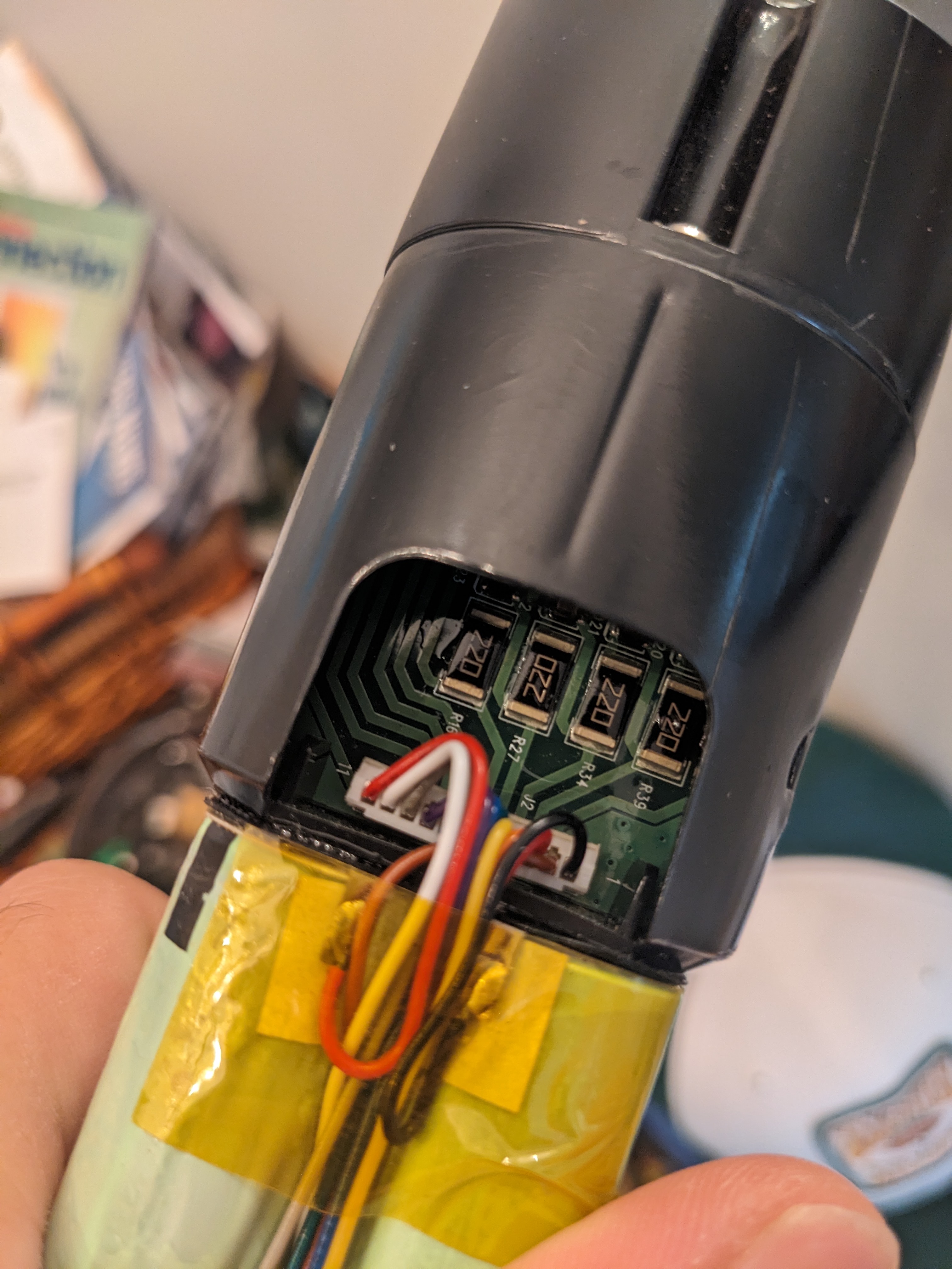
I purchased an e-bike which was advertised as just needing the batteries replaced. The li-ion batteries had been sitting dead for months. Once I got the battery removed it was clear that was not the case. You can see the hole where the plastic melted from this component overheating on the board. The burnt one is the same as those in the center of this photo.
What is it and how do I determine the correct replacement?
183
184
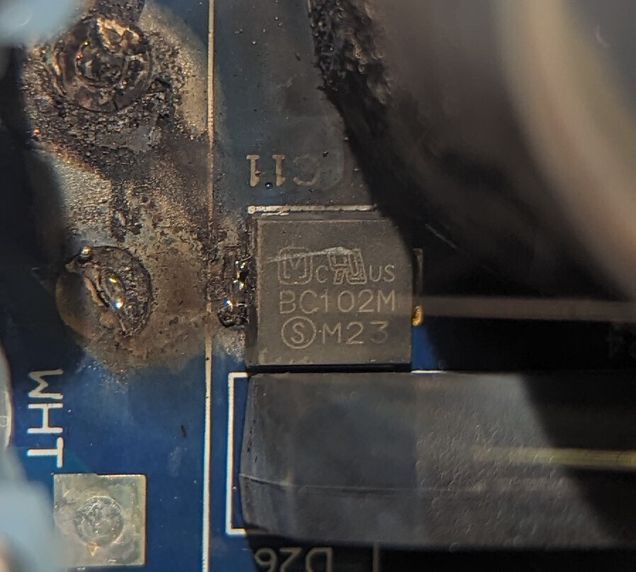
Trying to identify a component on a pool control board.
It's related to the T-Cell functionality of the board, since everything else like sensing, timing, and whatever else works on the board.
Component got water on it, most likely when a not uncommon occurrence of water jetting out from the filter and splashing onto the board eventually got where it shouldn't.
185
186
187
188
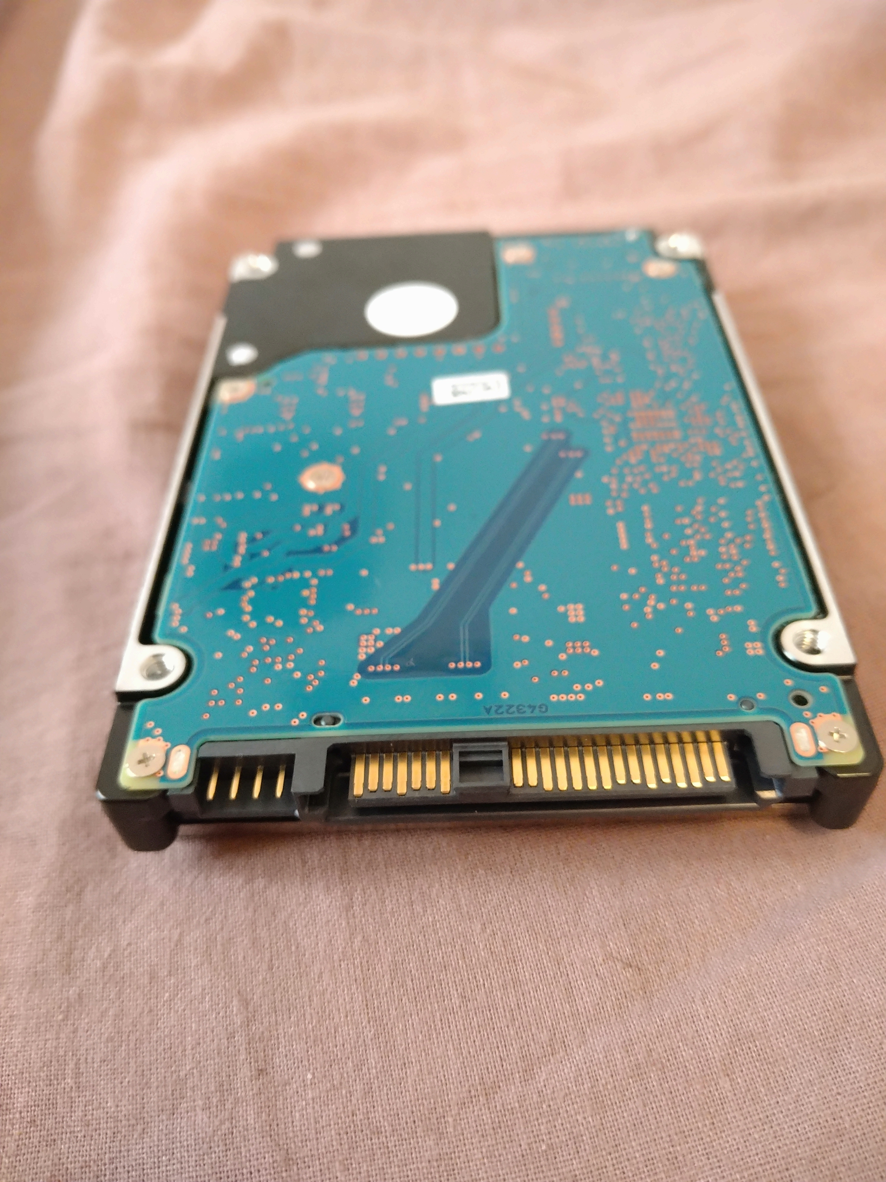
//Edit: It's a SAS drive. thanks for the help :))
I bought two of these a long time ago, and I recently tried to connect them to a SATA III connector without luck. The size seems to match up, but the block between the two pin segments seems to block it from connecting with SATA III.
Can you help me figure out what kind of adaptor I need ? :))
189
190
191
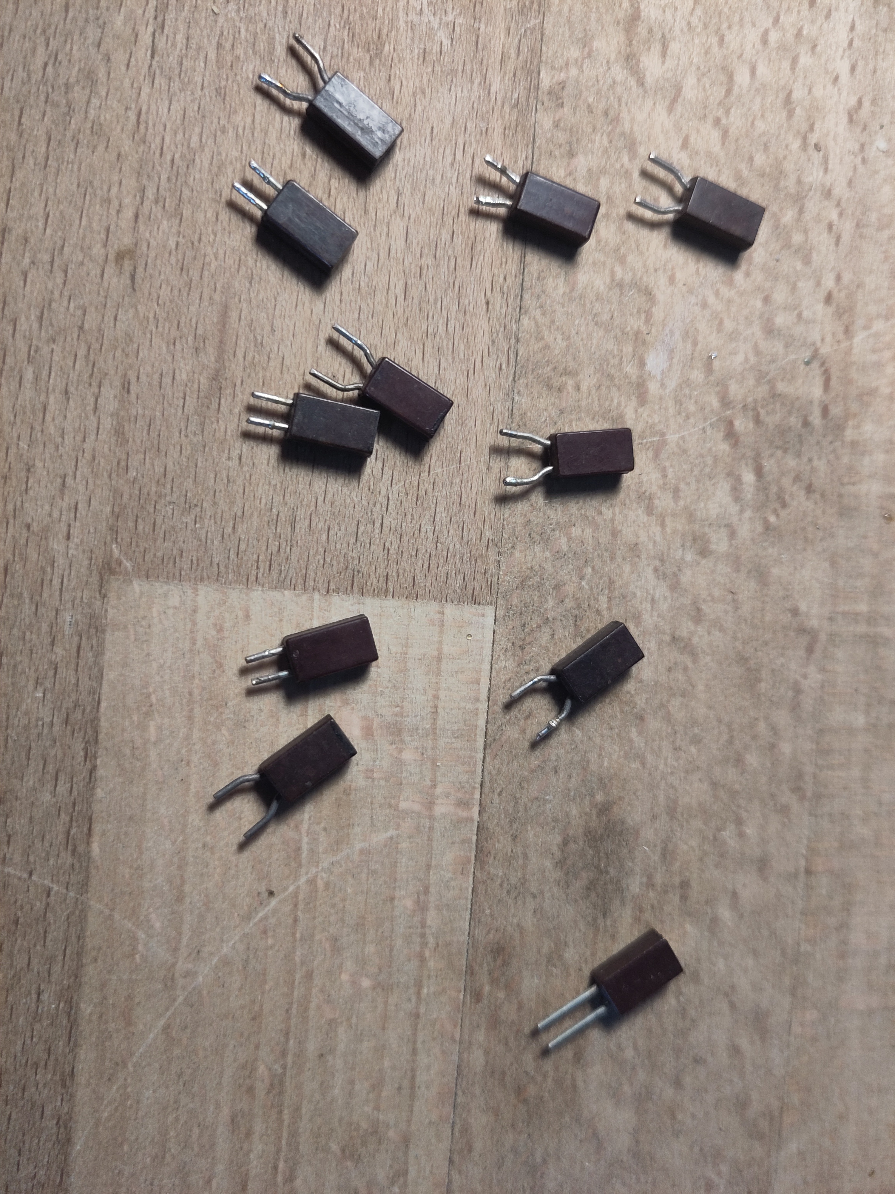
I have a whole bunch of them. They are possibly a bit older (70s, 80s) judging by other contents of the junk box they are from.
There are no labels of any kind, but on the top they have stripes that look hand painted.
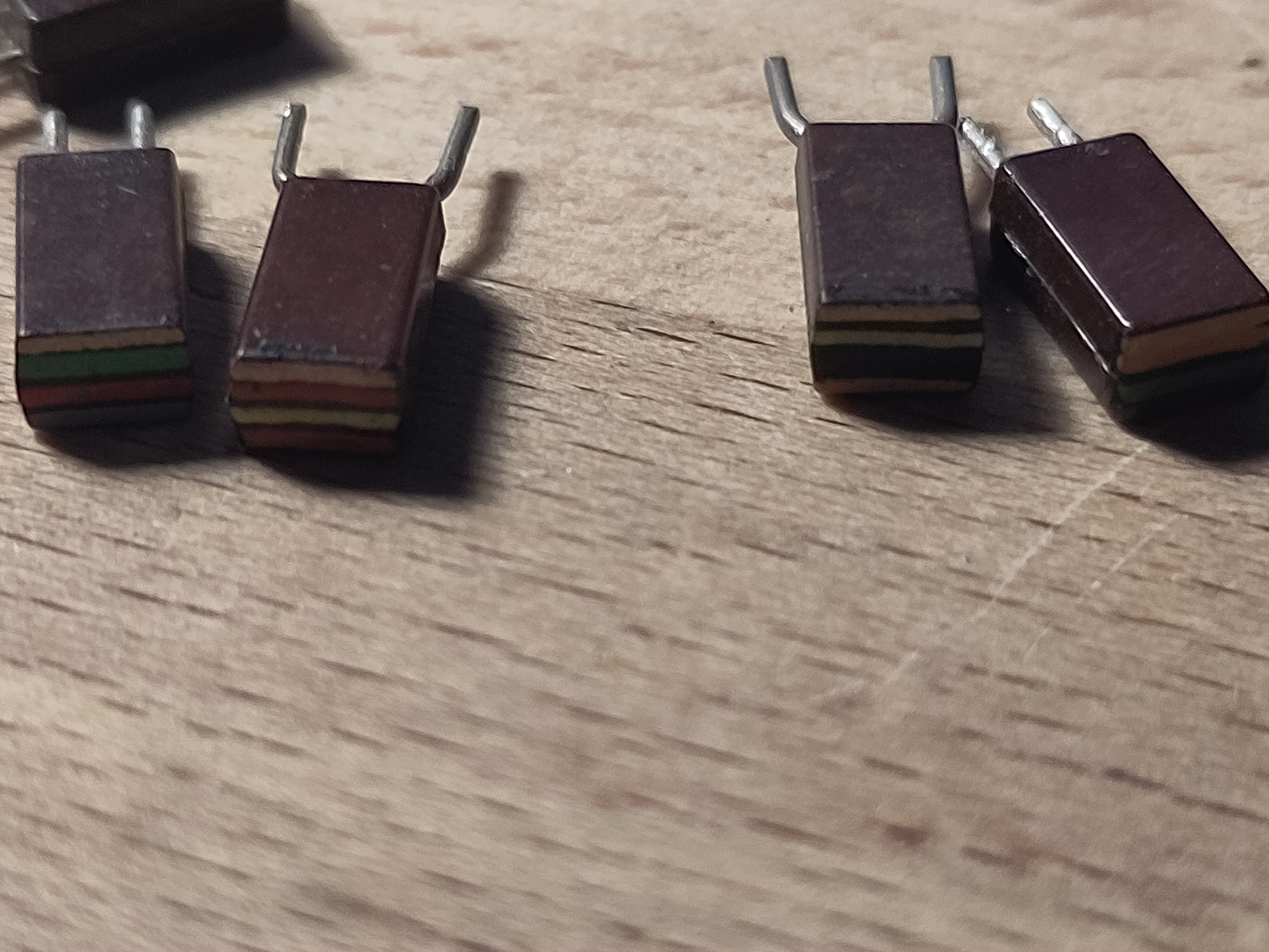
For at least some of them the resistance roughly corresponds to the color code.
So, I'm just curious why I can't find anything about these on the internet.
192
193
194
Circuit is for controlling the fan on a Raspberry Pi, just on/off according to temp, no PWM. Not sure about the diode as it has a .7V drop and it's a tiny brushless DC motor. No markings on the fan so I measured the current with a multimeter when hooking it up to a USB charger. Circuit was adapted from here using what I have on hand.
Suggestions? Any advice is greatly appreciated!
*EDIT: Confirmed, this circuit works on a Raspberry Pi 4. Base was wired to GPIO 17 and manually tested using commands:
raspi-gpio set 17 op dh
raspi-gpio set 17 op dl
I didn't use a breadboard, just hack-n-slash with the wires coming out of the fan, the leads on the thru hole components, a jumper connected to gpio 17 as a socket for the base/resistor lead, and heat shrink tubing for insulation. Folded it up as I closed the housing. Case combo including heatsinks and fan here.

195


197
1
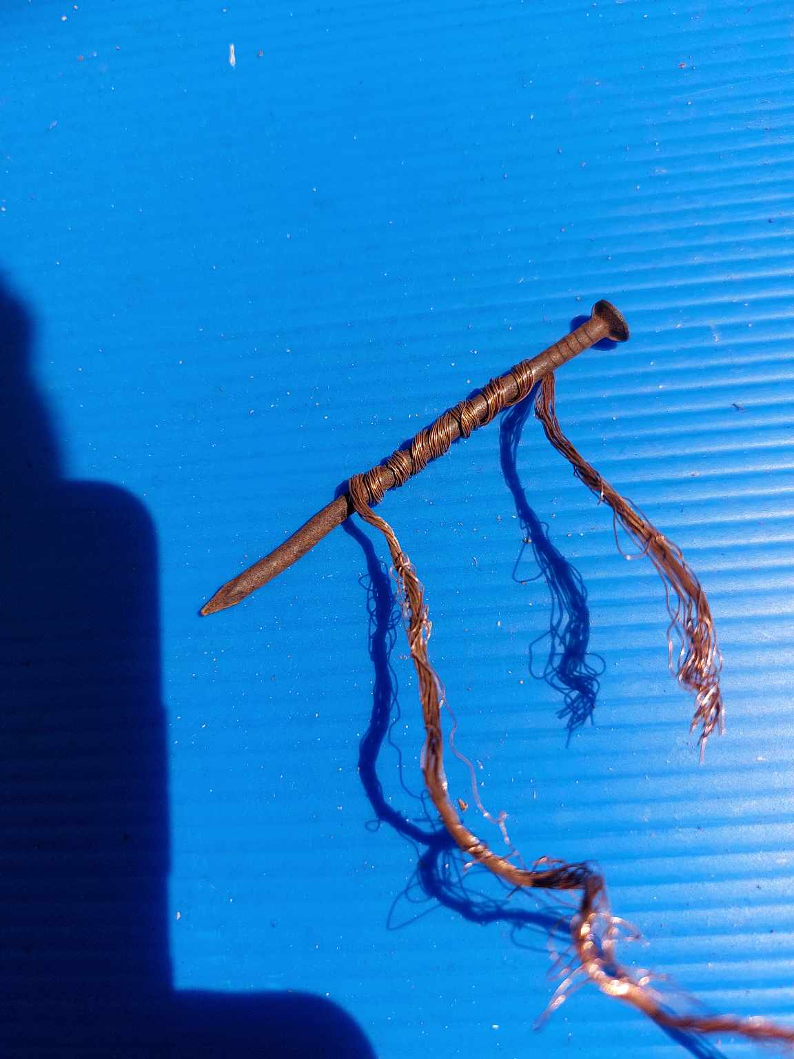
This is my electromagnet.
198
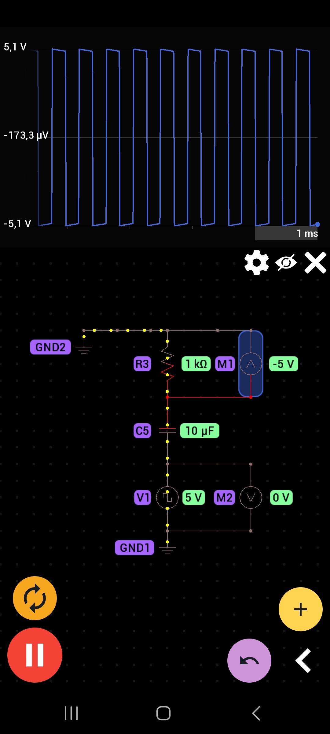
Hello there, This oscillator is a 0V +10v DC oscillator, which after current passes through the capacitor, it produces a -5v +5v AC on the resistor.
We've all heard that AC removes DC component and let's AC pass by. I understand the dynamics of this circuit in case the oscillator were operating with AC (capacitive reactance), however this oscillator is DC, the voltage across the capacitor never changes polarity (since the other side of circuit is ground), so what gives? And why the 10V DC is split on half +5 -5 volts after the capacitor? Thank you!
199
200
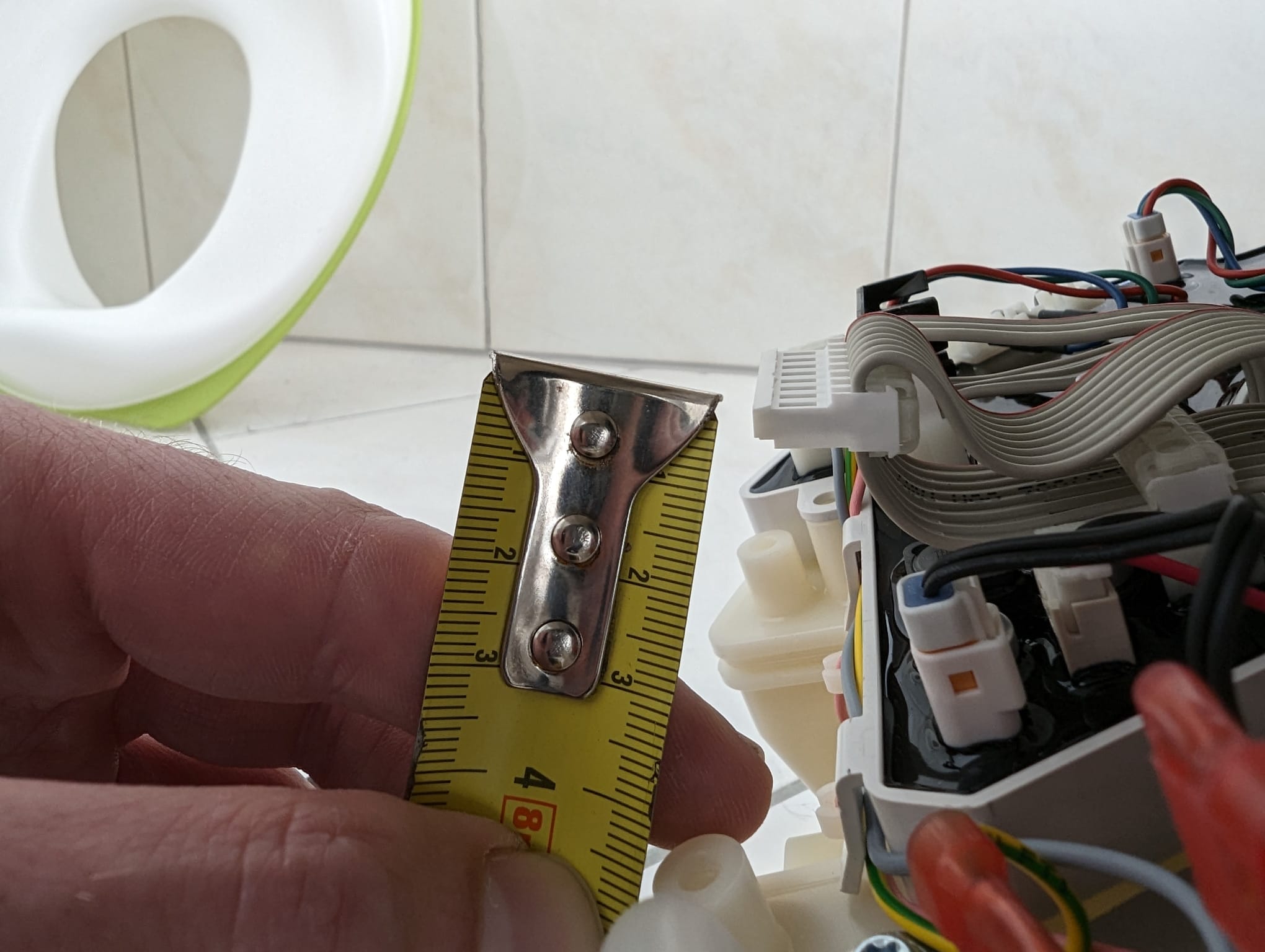
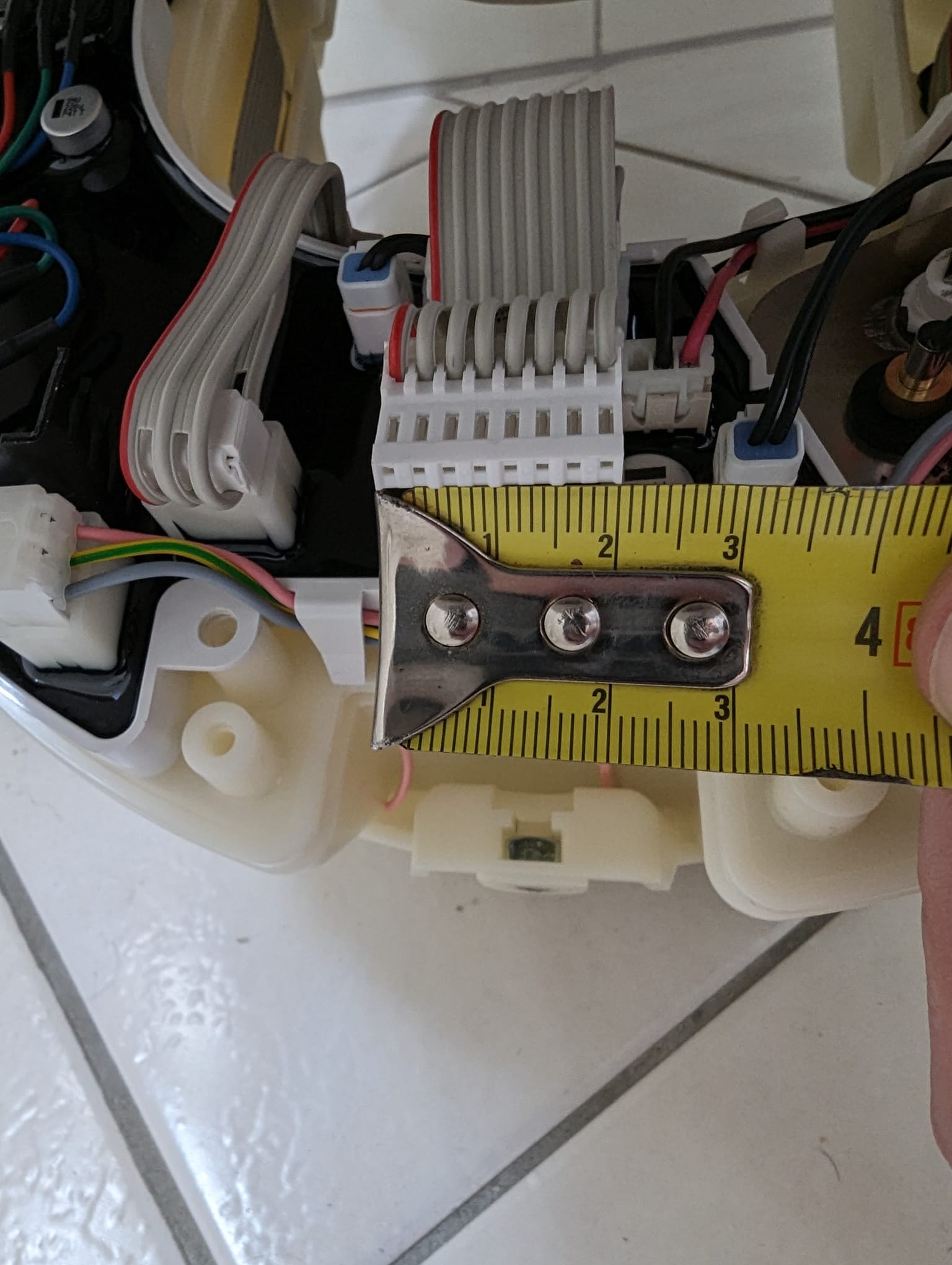
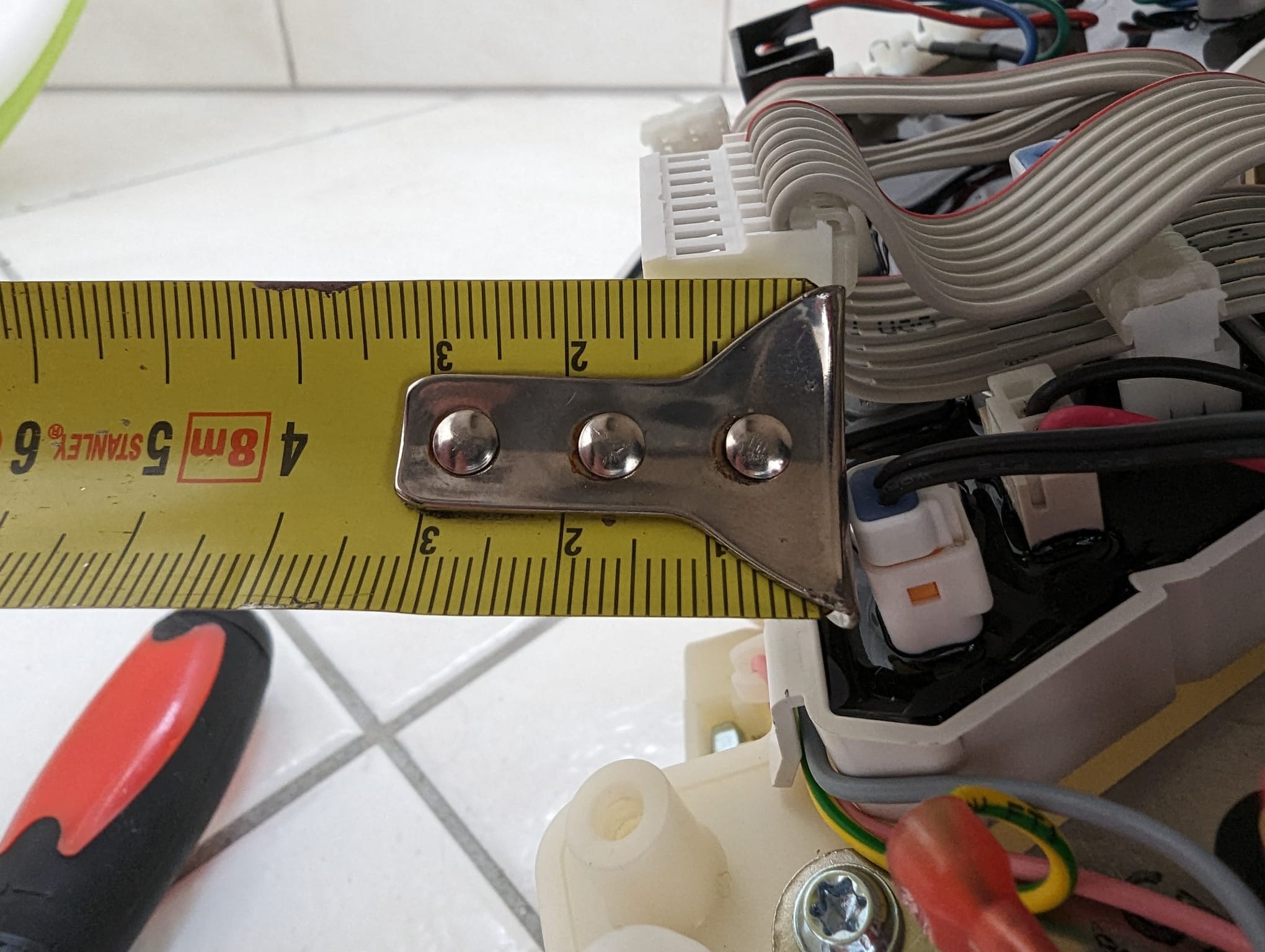
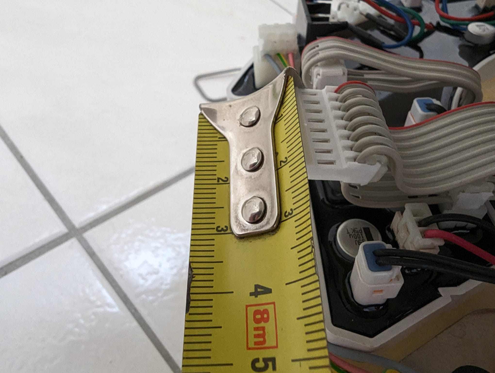
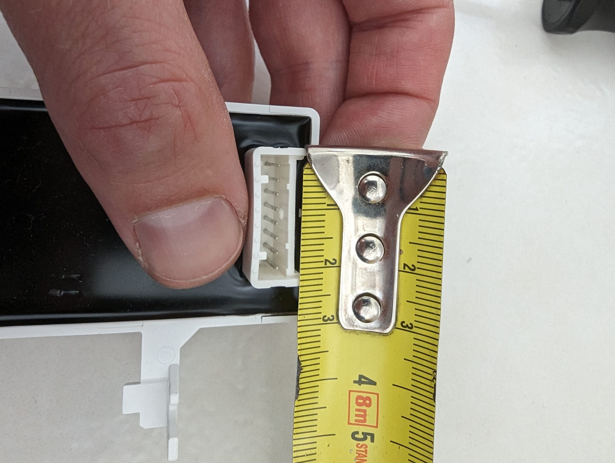
Hi!
I have bought a Geberit shower toilet/bidet with a motion sensor but it's aimed at the front while the toilet is installed sideways. So I've opened the thing up and I can take out the motion sensor, but the cable it's connected to is too short to do anything with. So I'm looking to buy/make an extension cable, but I have no idea on how to find it. So I took pics of the connector and I'm hoping you can help me find the type of connector (and if someone has a buy link: even better!). Thanks!
edit: https://www.jst.com/products/insulation-displacement-connectors-wire-to-board-type/vr-connector/ this looks like the socket, but the pitch seems wrong?