I'm new to freecad, so far I made it this way :
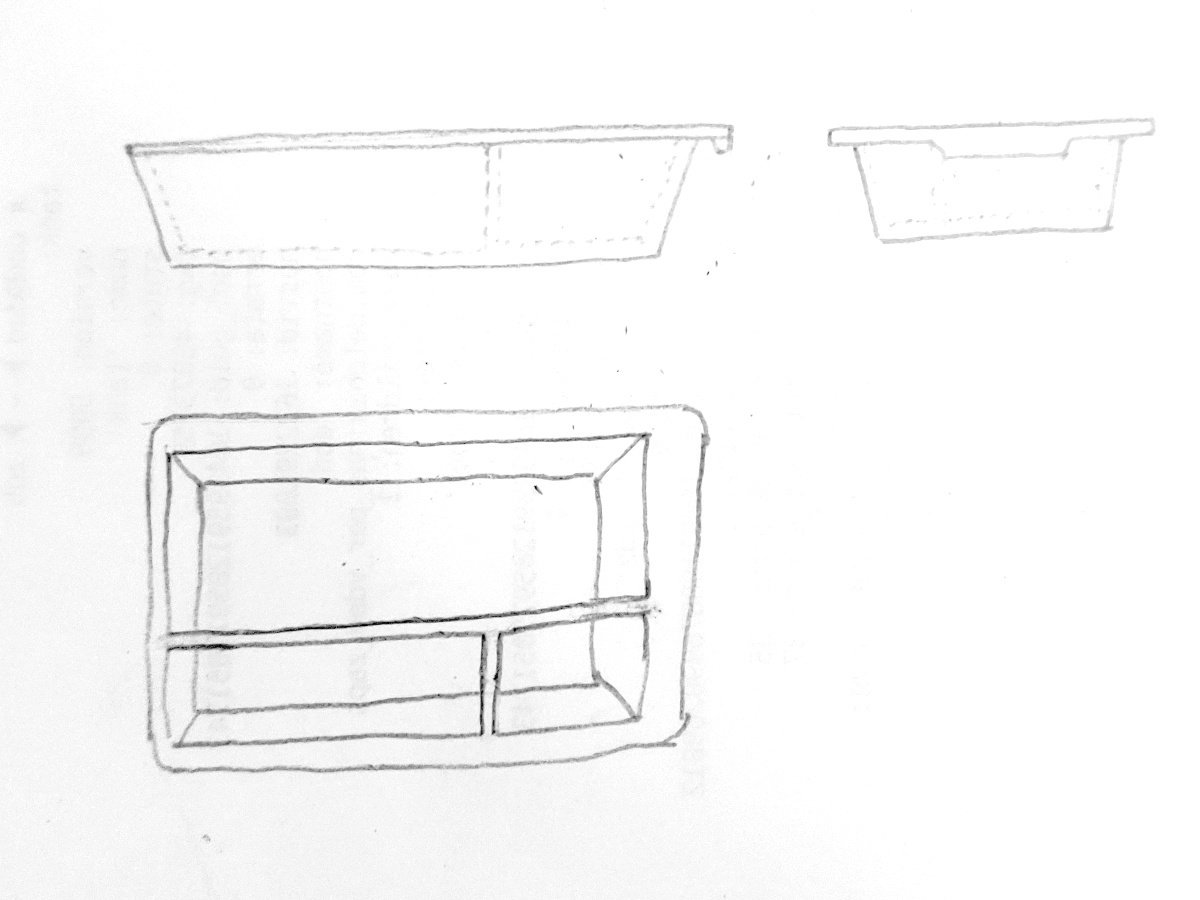
Sketch a rectangle for the top surface, pad it, add filets for the corners. Then select to bottom face, make a new sketch, another rectangle, then a datum plane 40mm below, sketch another smaller rectangle, and make a loft between the two to create the bottom of the tray.
Now for the hole I made a rectangle on the top face and made a pocket with an angle.
Downside of this, the thickness of the walls is not equal. Ideally I'd like a 1.5mm thickness everywhere. And I'm not really sure how to proceed to make the separators inside the tray.
What is the most efficient way to do it? thanks
Use the Part Design workbench (you probably are already, but no one's said it yet). Sketch a rectangle for the top of the whole tray, not the surface. Pad it down 40mm. Add a draft to set the angle of the sides. Use the thickness tool to dig out the middle of the top face - to a thickness of your exact choosing, which will be consistent everywhere. Now you have a trapezoidal bin.
Then how do you make the separators. Um, draw a sketch with the tee on the inside bottom and pad it... and then the separators don't reach the angled side walls. Oo, how about this: on the inside bottom, draw a sketch of the small square of material at the junction of the tee, and pad this tiny pillar up to the top of the tray. Then start a sketch on a side wall, External Geometry the near sides of the pillar in, and they'll be projected onto the angled side wall. Then loft the two rectangles together. Yeah? Yeah? No. That didn't work. The projection was normal to the angled wall, not to the side of the pillar.
HAHAHA ok. Select a side of the pillar. Pad it, select Up to Face, and pick the angled inside . Presto!
Then stick the lip on top and the grippy bit and that.
I hope this was helpful and entertaining.
thanks, I'll try that. so far I only used the Part Design and Sketecher workbenches, I'll try the Draft.
To be clear, I'm pretty sure that poster was referring to the Draft tool in the PartDesign workbench:
...And not the Draft workbench, if that's where you were going.
Oh! Oh yeah, that's what I meant, sorry