this post was submitted on 26 Aug 2024
82 points (94.6% liked)

Technology

58306 readers
3182 users here now

This is a most excellent place for technology news and articles.


Our Rules


  1. Follow the lemmy.world rules.
  2. Only tech related content.
  3. Be excellent to each another!
  4. Mod approved content bots can post up to 10 articles per day.
  5. Threads asking for personal tech support may be deleted.
  6. Politics threads may be removed.
  7. No memes allowed as posts, OK to post as comments.
  8. Only approved bots from the list below, to ask if your bot can be added please contact us.
  9. Check for duplicates before posting, duplicates may be removed

Approved Bots


founded 1 year ago
MODERATORS
 

Edit: It is! I got the WiFi replaced and functional.

I need a confirmation that this is an accurate diagram, I have a A+E-key WiFi adapter, and I need to use it to replace a E-key WiFi adapter. I cannot find much information about compatibility, and need some confirmation before I stick my adapter in a type-e slot.

you are viewing a single comment's thread
view the rest of the comments
[โ€“] potentiallynotfelix@lemdro.id 3 points 1 month ago (1 children)

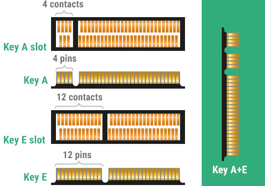
No worries, my card has 4 on one side and 3 on the other, so I don't believe that will be an issue. I thought that you were more concerned about the slight difference in the pin's location from top to bottom of the slot diagram.

[โ€“] over_clox@lemmy.world 1 points 1 month ago

Cool cool. I was worried that it might be a piss poor diagram made by a 10 year old just learning Photoshop or something.

When it comes to electronic diagrams, I'm used to seeing complete pinouts that label every single pin, like ground, power, data and clock signals and whatnot.

Seeing such an incomplete diagram like this one just scares me though.