cross-posted from: https://lemmy.ca/post/703695
Yesterday I posted a picture of a little tact switch that I installed on a piece of protoboard with a hardware debounce circuit on the bottom. I love those little things and thought I would share a how to for making them.
The first thing you need is the little piece of PCB. I had a bunch of these Altoids Tin protoboards made up a few years ago.

I break them down into smaller pieces,

then I break those down to the size that I need,

then I sand the edges to make them pretty (and also to make them small enough to sit beside each other if I need more than one.

Note that the board consists of four columns of 3 connected pads and four columns of 2 connected pins.
Next, I assemble (almost) all of the components that I'm going to need. These are (top to bottom, left to right) 1 uF 0804 capacitors, 1 K 0804 resistors, and 10 K 0804 resistors, the little sanded piece of PCB, three r-pin pieces of header strip (I like to use one red, one blue, and one black but you can use all black or any other color you want), and a 5 mm x 5 mm tact switch (I like the ones with the 7 mm shaft as shown because I can put a cap on them but any old tact switch will do.) Missing from this picture is a

First, we're going to install the debounce components on the bottom of the board. With the columns of 2 at the top and the columns of 3 at the bottom you're going to bridge the gap on the second column with the little jumper wire and the third column with the 10 K resistor. Next you're going to bridge the top end (at the 2-pin column side) of the little wire and the 10 K resistor with the 1 uF capacitor. Finally, you're going to bridge the bottom of the right two 2-pin columns from the pint where the 1 uF capacitor and 10 K resistor meet to the bottom of the last column leaving the hole unobstructed. It will look like this:


The next part is tricky. You have to push some of the pins on the header strips through. On the black one and the red one (or two of the black ones) you're going to push three of the pins through from the long side. On the blue one you're going to push through one of the pins from the long side as shown.

Now, push the header strips into a breadboard as shown. The pins that you pushed through do not go into the breadboard, they stick up into the air. It's important that the pins that you didn't push through on the red and black strips line up with the one that you did push through on the blue strip as shown.

Next, put the PCB over the pins as shown. The soldered components should be on the bottom of the board facing the breadboard. Make sure that the point where the capacitor and two resistors meet is in line with the three special pins on the header strips. If thy don't you can turn all of the header strips around and try again.

Next, clip the pins you pushed through, the ones stick up into the air, off flush with the PCB.

Now, push the ends of the short pins you didn't push through and cut off down flush with the surface of the PCB.

Check one more time that the three special pins and the point where the three components meet are lined up then solder the pins marked with an X.

Now, grab your tact switch. Note that the legs have bumps in them to help hold them in the holes while you solder them.

Use a pair of smooth jawed plyers to squeeze the legs straight then bend two pins out at 90 degree angles as shown.

Trim off the ends of the pins you bent.

Insert the tack switch into the PCB as shown. The bent pins will be over the two pins in the blue row that you didn't solder above. You will need to bend the bent pins out a bit to make them reach the middle of the pads.

Now, solder all four pins pushing down on the body of the switch to make sure it's tight to the PCB and lined up square to the board.
Once you've soldered the switch in place flip it over and make sure that there is a good connection between the end of the 1 K resistor and the pin of the switch. Add a bit of solder if you need to.

Now you can plug the switch into your breadboard and add a Dupont wire or jumper wire to the pin of your MCU.

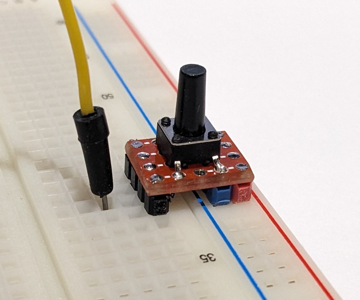
Note that the red header strip and blue header strip match up with the red and blue rails on the breadboard. This switch can only be installed on this side of the breadboard to get a debounced going low switch. The construction of a switch for the other side of the breadboard is exactly the same but you switch the position of the red and blue header strips.
This is what one of these little switches looks like in a project. This is a prototype for a ROM switching and RESET circuit I'm going to build into a 23xx to 27256 ROM adapter for the Commodore 64.

